Joints
To configure the emergency stop ramps, see chapter Emergency stop ramps and software limit switches of the joints.

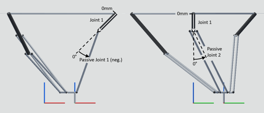
In addition to the joint axes, 6 non-driven joints are to be configured. These act as software limit switches.
Passive joints 1 and 2 refer to arm 1 and are shown in the figure. Passive joints 3/4 or 5/6 refer to arm 2 or 3, respectively, and their function corresponds to that of passive joints 1 and 2 when turned in a rotationally symmetric manner.
Parameter name | Additional information |
|---|---|
Elbow angle 1 | Angle between linear axis 1 and lower arm 1 in the vertical plane in which linear axis 1 moves. |
Shear angle 1 | Angle between the vertical plane in which the linear axis 1 moves and the forearm 1. |
Elbow angle 2 | Angle between linear axis 2 and lower arm 2 in the vertical plane in which linear axis 2 moves. |
Shear angle 2 | Angle between the vertical plane in which the linear axis 2 moves and the forearm 2. |
Elbow angle 3 | Angle between linear axis 3 and lower arm 3 in the vertical plane in which linear axis 3 moves. |
Shear angle 3 | Angle between the vertical plane in which the linear axis 3 moves and the forearm 3. |
