Examples
Example 1: CARTESIAN_GANTRY_LLR_M10
The CARTESIAN_GANTRY_LLR_M10 kinematic model has the Cartesian degrees of freedom X, Y and RotZ in the BASE coordinate system BCS in the default setting (Cartesian assignment 0). The joint axis 1 moves along BCS_X and the joint axis 2 along BCS_Y. Joint axis 3 rotates about BCS_Z. See CARTESIAN_GANTRY_LLR_M10. Since KCS and BCS are identical in this assignment, the joint axes point in the corresponding directions of the KCS.
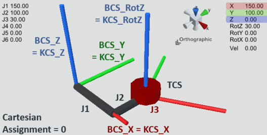
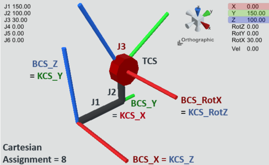
If now, for example, joint axis 1 should move along BCS_Y instead, and joint axis 2 should move along BCS_Z, and joint axis 3 should move about BCS_X, proceed as follows:
The kinematic model is aligned with the kinematic coordinate system KCS relative to the BASE coordinate system BCS. Since joint axis 1 corresponds to the KCS_X direction and this should point in the direction of BCS_Y, KCS_X must therefore point in the direction of BCS_Y. Joint axis 2 corresponds to the KCS_Y direction, and this should point in the BCS_Z direction. Since the coordinate systems used are right-handed, KCS_Z must point in the direction of BCS_X. Using KCS_X = BCS_Y and KCS_Y = BCS_Z, we now select the row in the above table where this is satisfied (using columns 2-4 or 5-7). This is the Cartesian assignment 8.
Cartesian assignment | Orientation of the BASE coordinate system relative to the kinematic coordinate system | Orientation of the kinematic coordinate system relative to the BASE coordinate system | ||||
|---|---|---|---|---|---|---|
BCS_X | BCS_Y | BCS_Z | KCS_X | KCS_Y | KCS_Z | |
8 | KCS_Z | KCS_X | KCS_Y | BCS_Y | BCS_Z | BCS_X |
Example 2: SCARA_RRR_M20
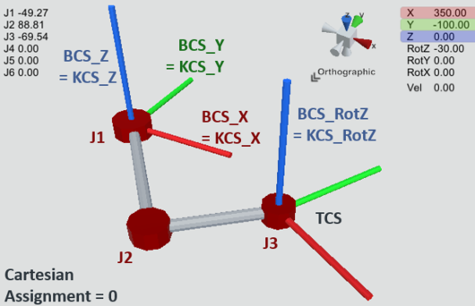
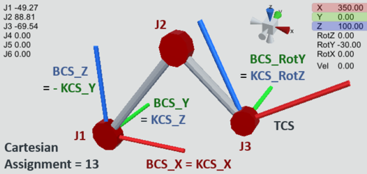
The SCARA_RRR_M20 kinematic model has the Cartesian degrees of freedom X, Y and RotZ in the BASE coordinate system BCS in the default setting (Cartesian assignment 0) with rotation of the 3 joint axes about BCS_Z. Since KCS and BCS are identical in this assignment, the joint axes rotate about KCS_Z accordingly. See SCARA_RRR_M20.
If, for example, the joint axes should rotate about BCS_Y instead, proceed as follows:
The kinematic model is aligned with the kinematic coordinate system KCS relative to the BASE coordinate system BCS. Since the 3 joint axes rotate about the direction of KCS_Z and these should now rotate about the BCY_Y direction, KCS_Z must point in the direction of BCS_Y. The X-axis should remain unchanged in this case. Using KCS_Z = BCS_Y and KCS_X = BCS_X, we now select the row in the above table where this is satisfied (using columns 2-4 or 5-7). This is the Cartesian assignment 13.
Cartesian assignment | Orientation of the BASE coordinate system relative to the kinematic coordinate system | Orientation of the kinematic coordinate system relative to the BASE coordinate system | ||||
|---|---|---|---|---|---|---|
BCS_X | BCS_Y | BCS_Z | KCS_X | KCS_Y | KCS_Z | |
13 | KCS_X | KCS_Z | - KCS_Y | BCS_X | - BCS_Z | BCS_Y |
Example 3: TRIPOD_RRR_M10
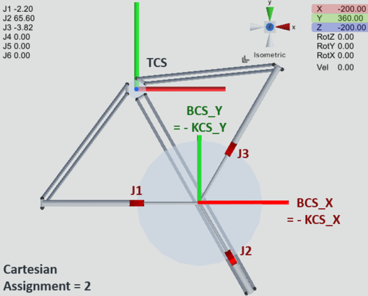
The TRIPOD_RRR_M10 kinematic model has the Cartesian degrees of freedom X, Y and Z in the BASE coordinate system BCS in the default setting (Cartesian assignment 0), where the joint axes are arranged in the top view in an offset of 120° counterclockwise with joint axis 1 on the Cartesian axis BCS_X. Since KCS and BCS are identical in this assignment, the joint axes point in the corresponding directions of the KCS. See TRIPOD_RRR/RRRR/RRRRR_M10.
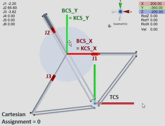
If, for example, the Cartesian axis BCS_X should run between the joint axes 2 and 3 instead, proceed as follows:
The kinematic model is aligned as desired with the kinematic coordinate system KCS relative to the BASE coordinate system BCS. In this example, KCS_X (i.e. the direction on which joint axis 1 is arranged) points in the -BCS_X direction and KCS_Y points in the -BCS_Y direction. KCS_Z points in the direction of BCS_Z, unchanged.
Using KCS_X = -BCS_X and KCS_Z = BCS_Z, we now select the row in the above table where this is satisfied (using columns 2-4 or 5-7). This is the Cartesian assignment 2.
Cartesian assignment | Orientation of the BASE coordinate system relative to the kinematic coordinate system | Orientation of the kinematic coordinate system relative to the BASE coordinate system | ||||
|---|---|---|---|---|---|---|
BCS_X | BCS_Y | BCS_Z | KCS_X | KCS_Y | KCS_Z | |
2 | - KCS_X | - KCS_Y | KCS_Z | - BCS_X | - BCS_Y | BCS_Z |
