Master-slave mode (P1-12 = 4)

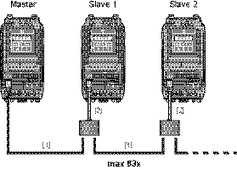
[1] | RJ45 to RJ45 cable |
|
|
[2] | Cable splitter |
|
|
The inverter has an integrated master-slave function.
Depending on the operating mode, the master‑slave function supports two different configuration options:
- Speed synchronism
- Load distribution
The two tables below describe the respective configuration of the inverters of both operating modes.
The master-slave communication is obtained via a special protocol. In this case, the inverter communicates via the RS485 engineering interface. Up to 63 inverters can be connected with one another in a communication network using RJ45 connectors. The maximum length of the communication network is 1000 m.
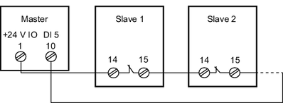
One inverter is configured as master, the remaining inverters as slaves. Each network may have only one master inverter. This master inverter sends its operating state (e.g. activated, deactivated) and its actual motor speed every 30 ms. The slave inverters then follow the state of the master frequency inverter.
INFORMATION

Cable set B can be used for setting up the master-slave network. It is not necessary to use a terminating resistor. For information on the cable sets, refer to the catalog.
