Integrating the inverter into an EtherCAT® network
The following device topology is used in the example:
- Higher-level controller (PLC) CX2020 from Beckhoff Automation GmbH with EtherCAT® extension EK1110
- MOVIDRIVE® modular application inverter, MDD90A double-axis module (CiA402: MDDA90ACiA402)
- MOVIDRIVE® modular application inverter, MDA90A single-axis module with MOVISAFE® CSS21A safety card (CiA402: MDA90ACiA402)
The following figure is a schematic representation of the device topology:
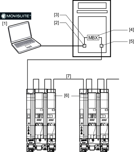
[1] | Engineering PC with MOVISUITE® | [5] | EtherCAT® interface of the EtherCAT® master |
[2] | Engineering interface of the EtherCAT® master | [6] | Inverter from SEW-EURODRIVE |
[3] | Internal IP routing | [7] | EtherCAT®/SBusPLUS interface of the inverters |
[4] | Mailbox gateway MBX |
|
|
For configuration and startup of the devices, the following tools are used:
- TwinCAT 3 from Beckhoff Automation GmbH for the PLC
- MOVISUITE® for inverters from SEW‑EURODRIVE
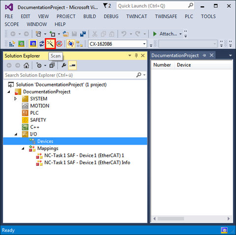
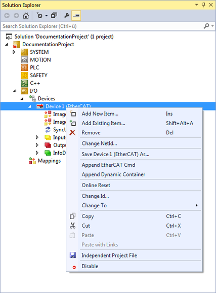
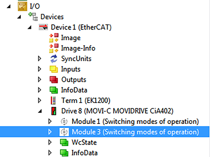
The inverter must be created in the I/O configuration of the EtherCAT® master.
Additional information
- EtherCAT®: Integrating an inverter by scanning the network
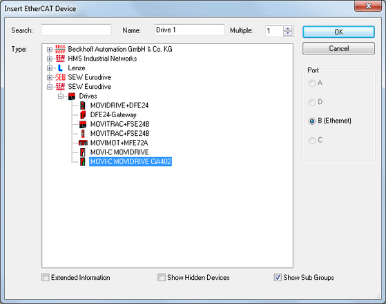
- EtherCAT®: Integrating inverters offline
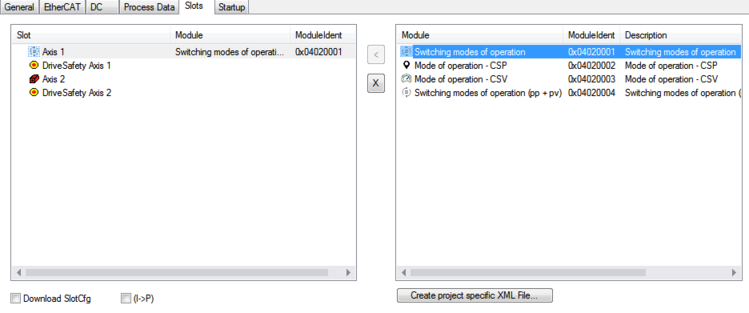
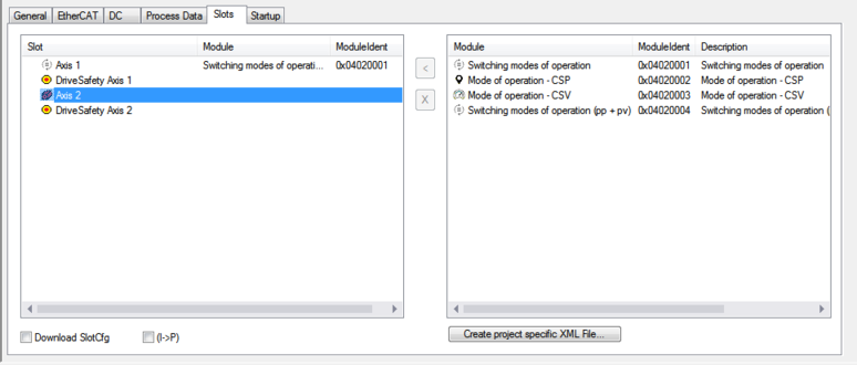
- EtherCAT®: Adjust the slot configuration, generate double-axis module
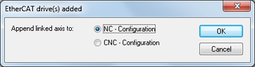
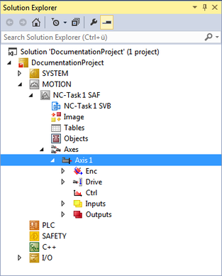
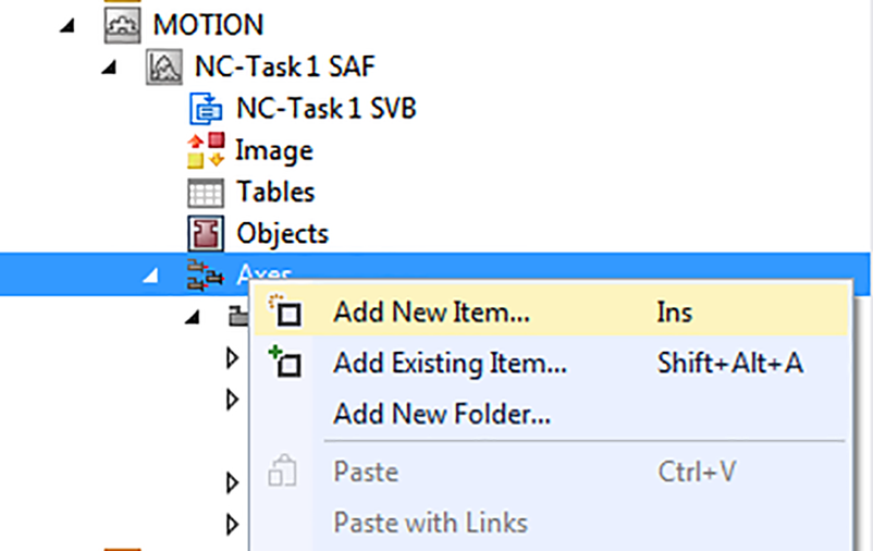
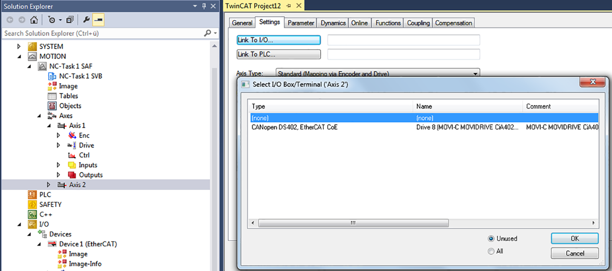
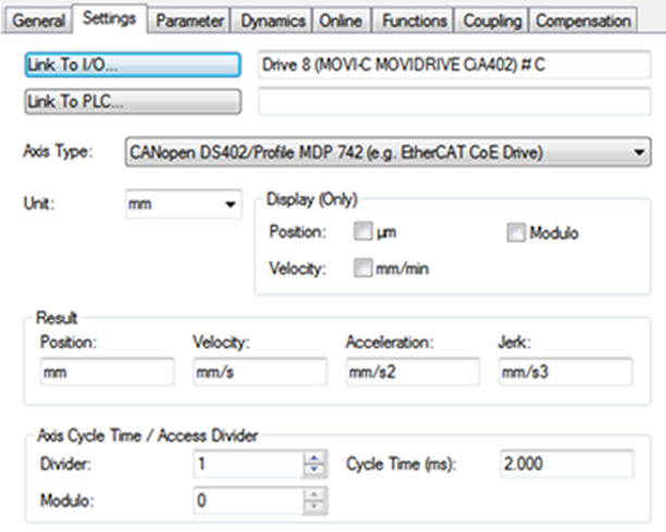
- Motion axis: Integrating inverters
- Motion Axis: Linking double-axis module
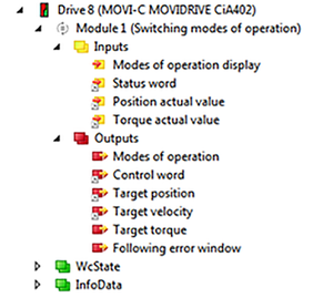
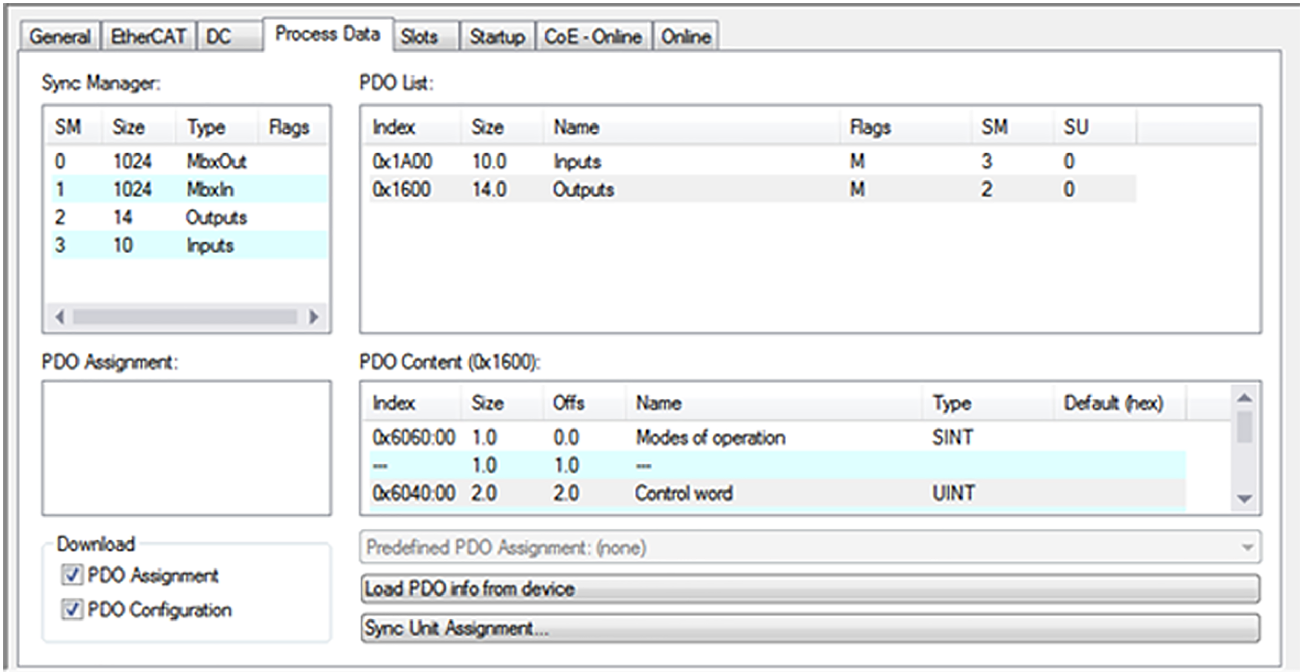
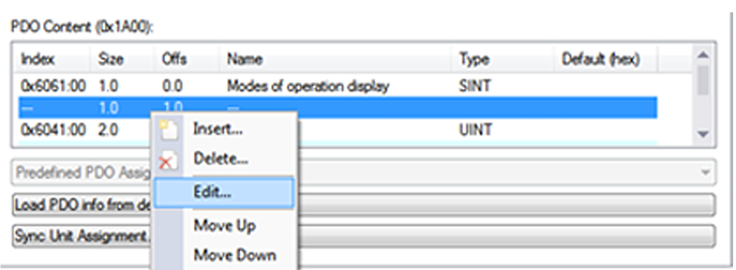
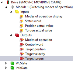
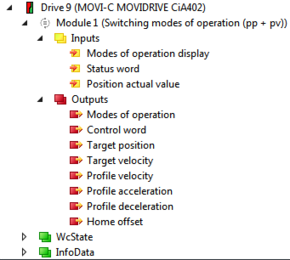
- Adapting the PDO image
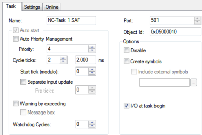
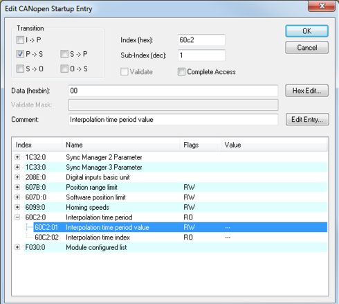
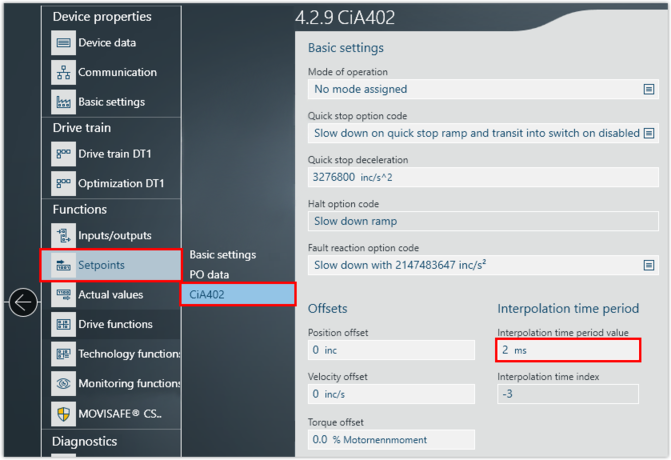
- Setting the interpolation time
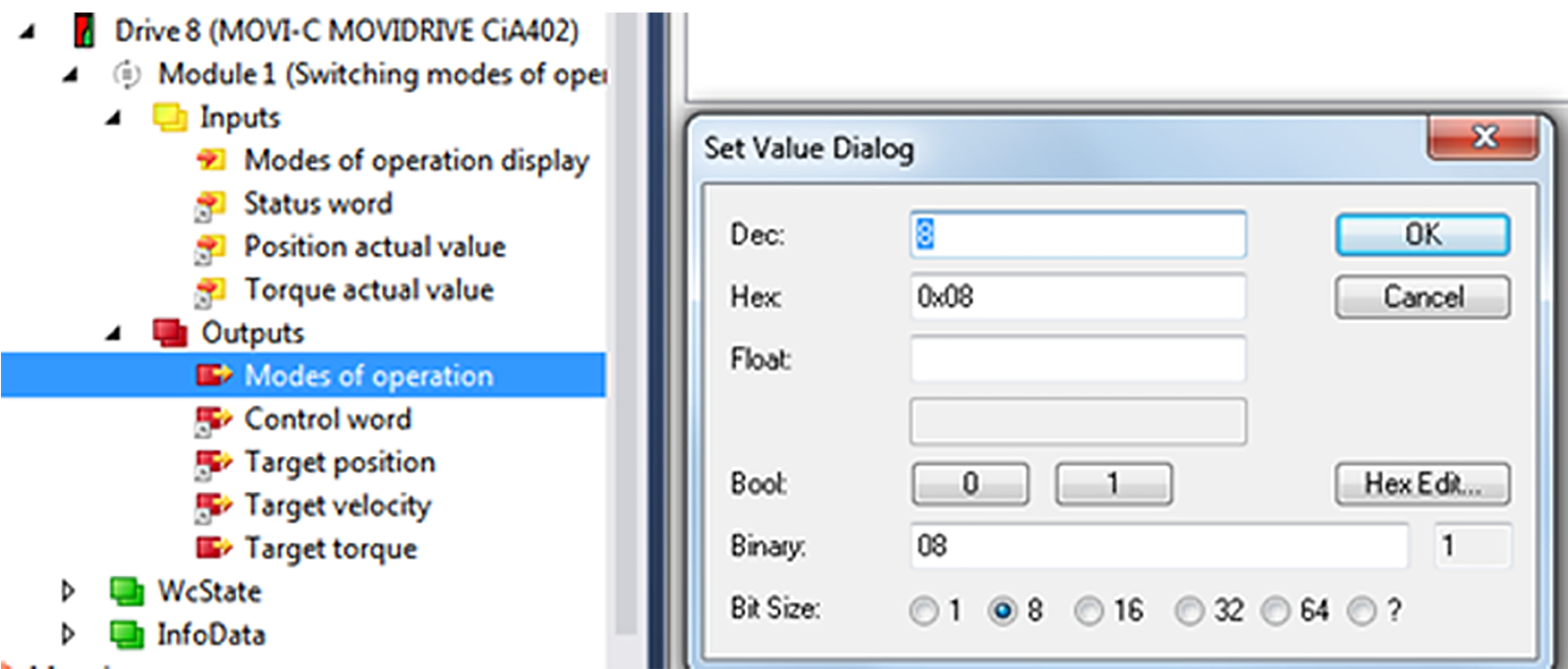
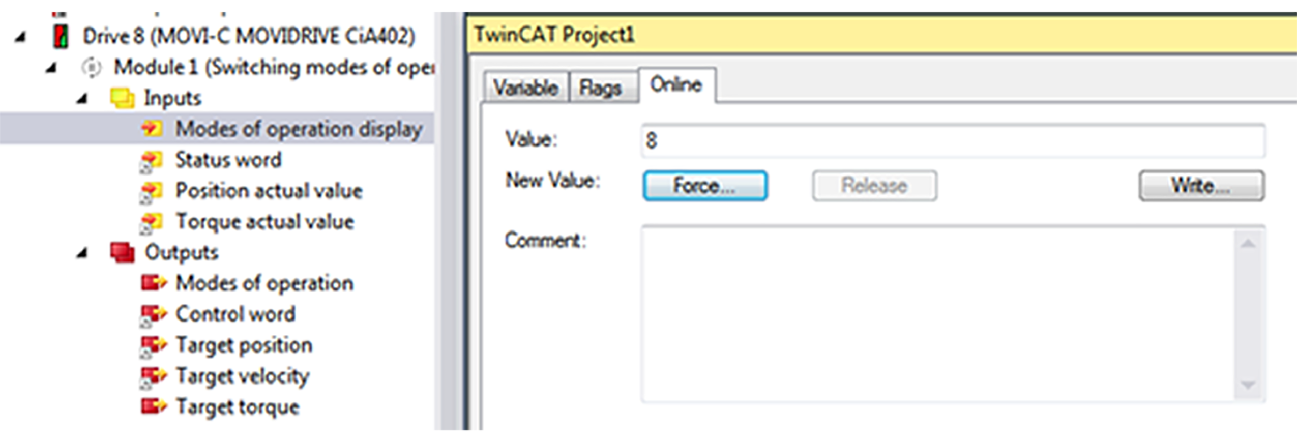
- Setting "Cyclic Synchronous Position" (csp) mode of operation
- Setting "Cyclic Synchronous Velocity" (csv) mode of operation
- Setting "Cyclic Synchronous Torque" (cst) mode of operation
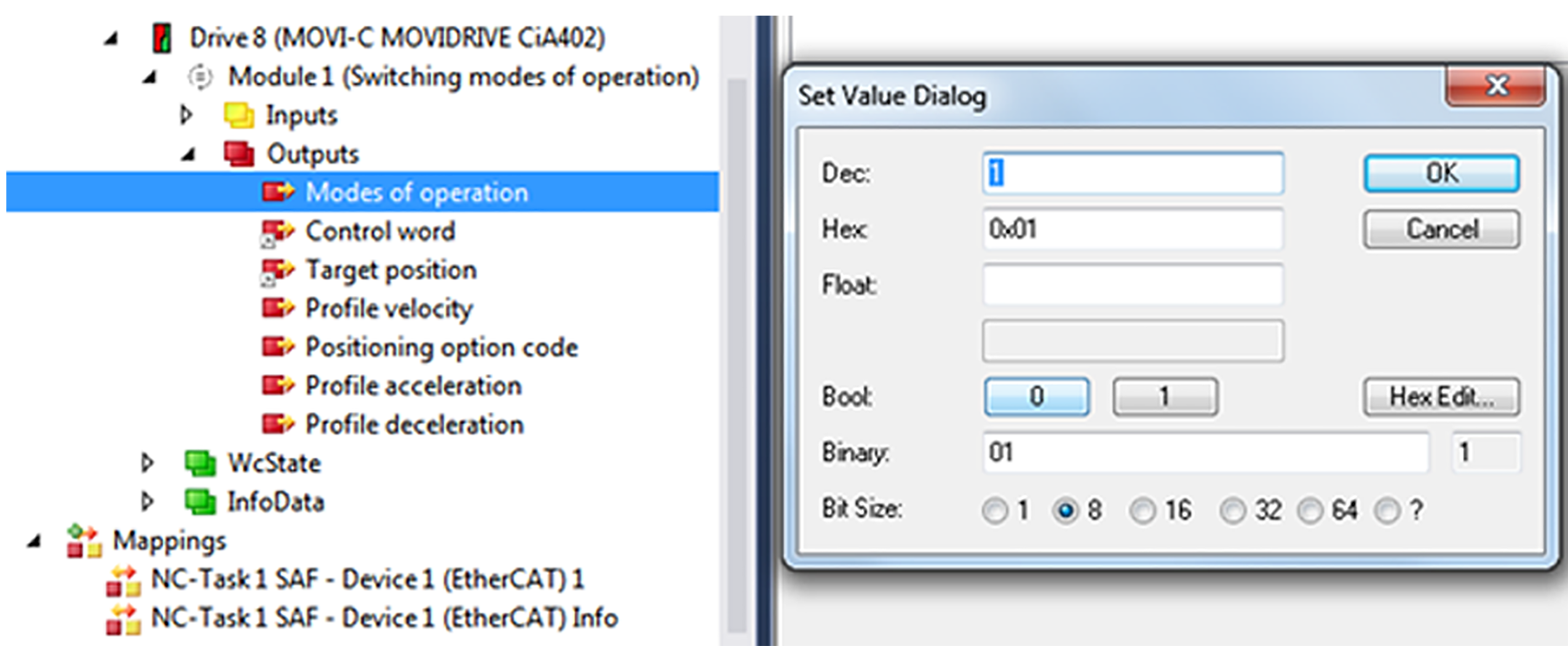
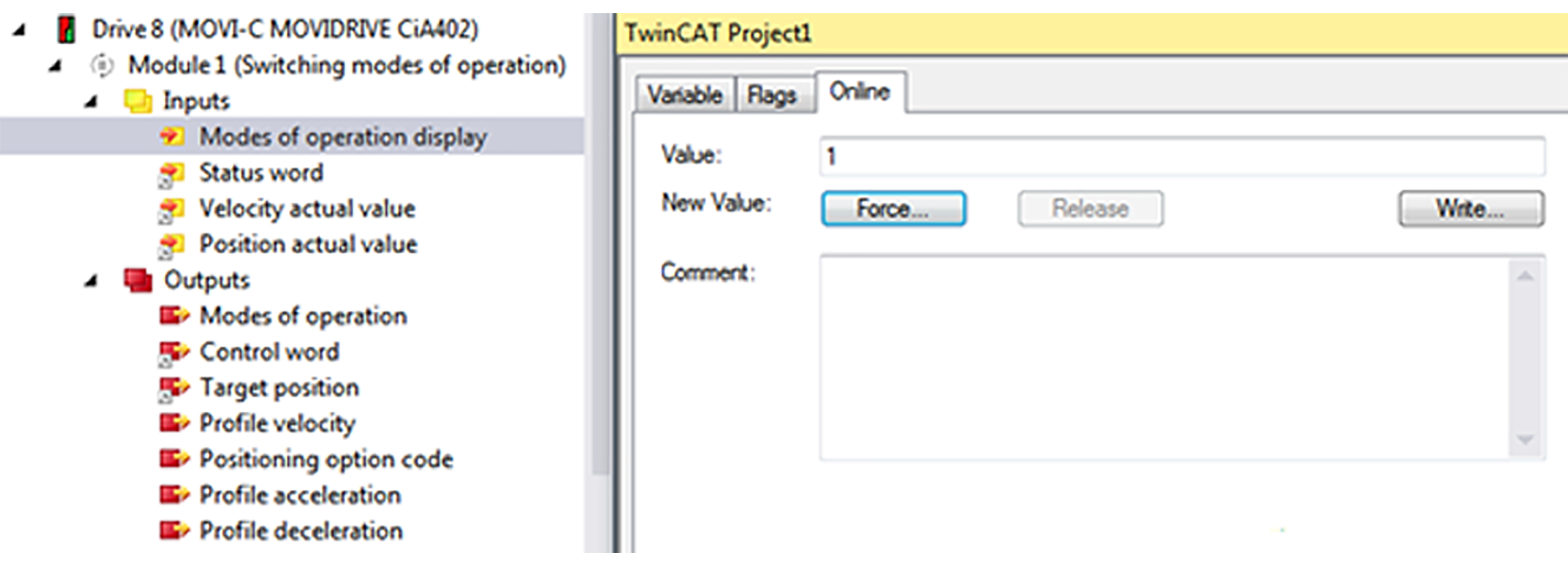
- Setting "Profile Position" (pp) mode of operation
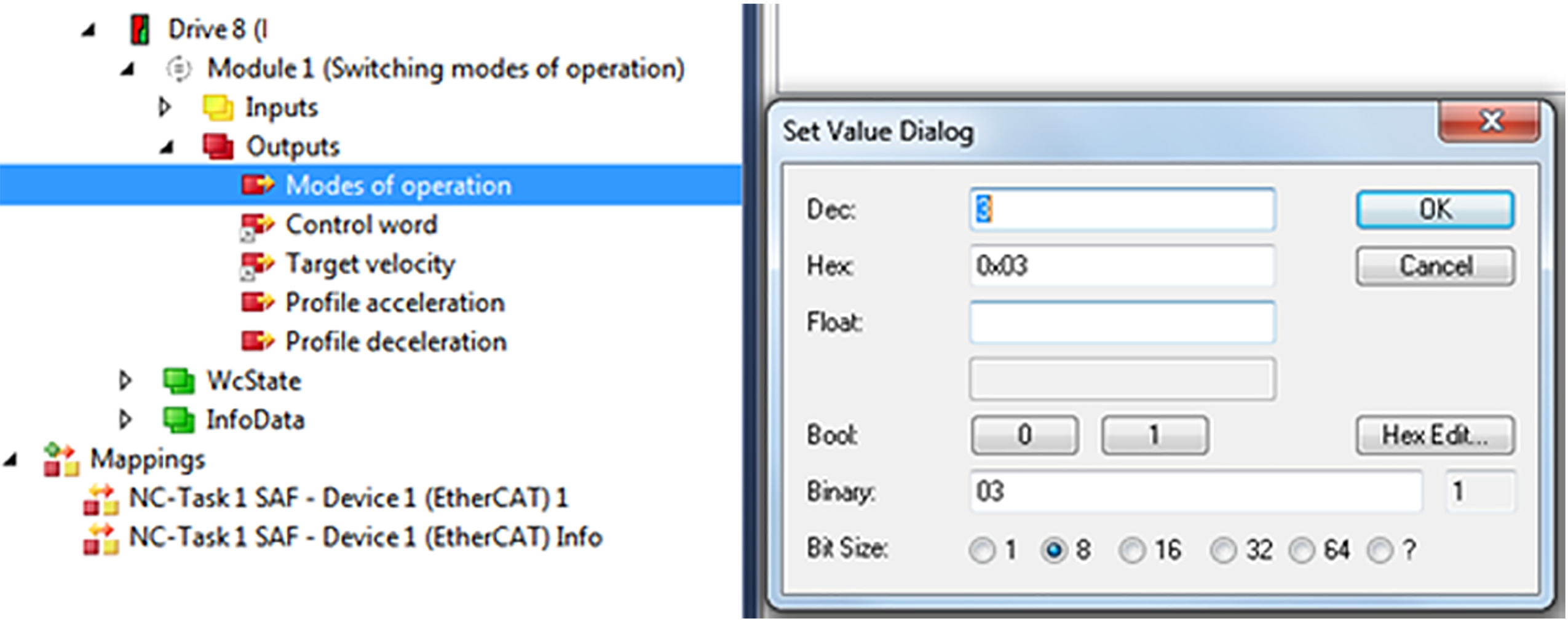
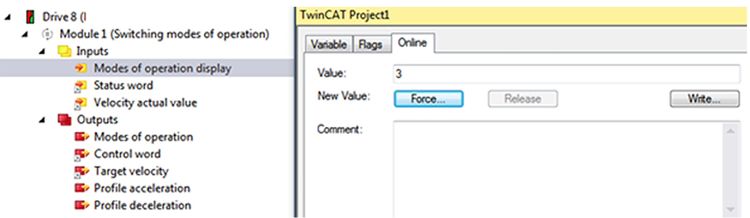
- Setting "Profile Velocity" (pv) mode of operation
- Using "Homing" (hm) mode of operation