Setting "Profile Position" (pp) mode of operation
This mode of operation can be used for relative or absolute positioning. The position profile will be calculated by the profile generator of the inverter.
The speed is always specified in inc s-1, while acceleration and deceleration are always specified in inc s-2.
The following example shows a conversion of the values:
Size | Value | ||
|---|---|---|---|
Speed | 1800 min-1 | 30 s-1 | 1966080 inc s-1 |
Deceleration/acceleration | 2 s | 15 s-2 | 983040 inc s-2 |
The following table shows the CiA402 objects which are required or recommended for the mode of operation. The objects do not absolutely have to be located in the cyclic PDO image.
Note the maximum number of 8 entries in the cyclic PDO image (see Adapting the PDO image).
Control | Feedback | ||
|---|---|---|---|
Mode of operation | Mode of operation display | ||
Control word | Status word | ||
Positioning option code |
| ||
Target position | Position actual value | ||
Profile velocity | Velocity actual value | ||
Profile acceleration | |||
Profile deceleration | Following error actual value (recommended) | ||
Following error window |
| ||
Following error timeout | |||
Proceed as follows:
- You have successfully started up the motor.
- You have integrated the inverter into the TwinCAT project via network scan or offline from the device catalog, linked it to a motion axis (see Motion axis: Integrating inverters) and transferred the corresponding process data object to the PDO image (Adapting the PDO image).
- You have already referenced the drive. If homing has been performed successfully, the "Homing attained" bit is reported in the status word ("Status word" process data object).
- If you want to adjust the PDO interface manually, set the required process data objects.
- The process data objects in the first two areas form the minimum configuration of the PDO interface. The profile values for speed, acceleration and deceleration can be changed during operation.
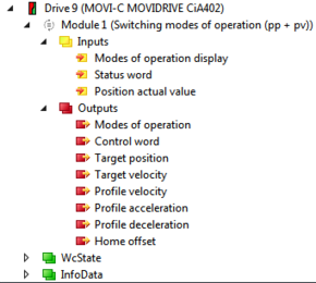
- If you want to use the predefined "Switching modes of operation (pp+pv)" module, select the functionally fixed module in the "Slots" tab (see Motion axis: Integrating inverters).
- This mode of operation is usually used without a motion axis. Set the profile values directly via the PDO interface.
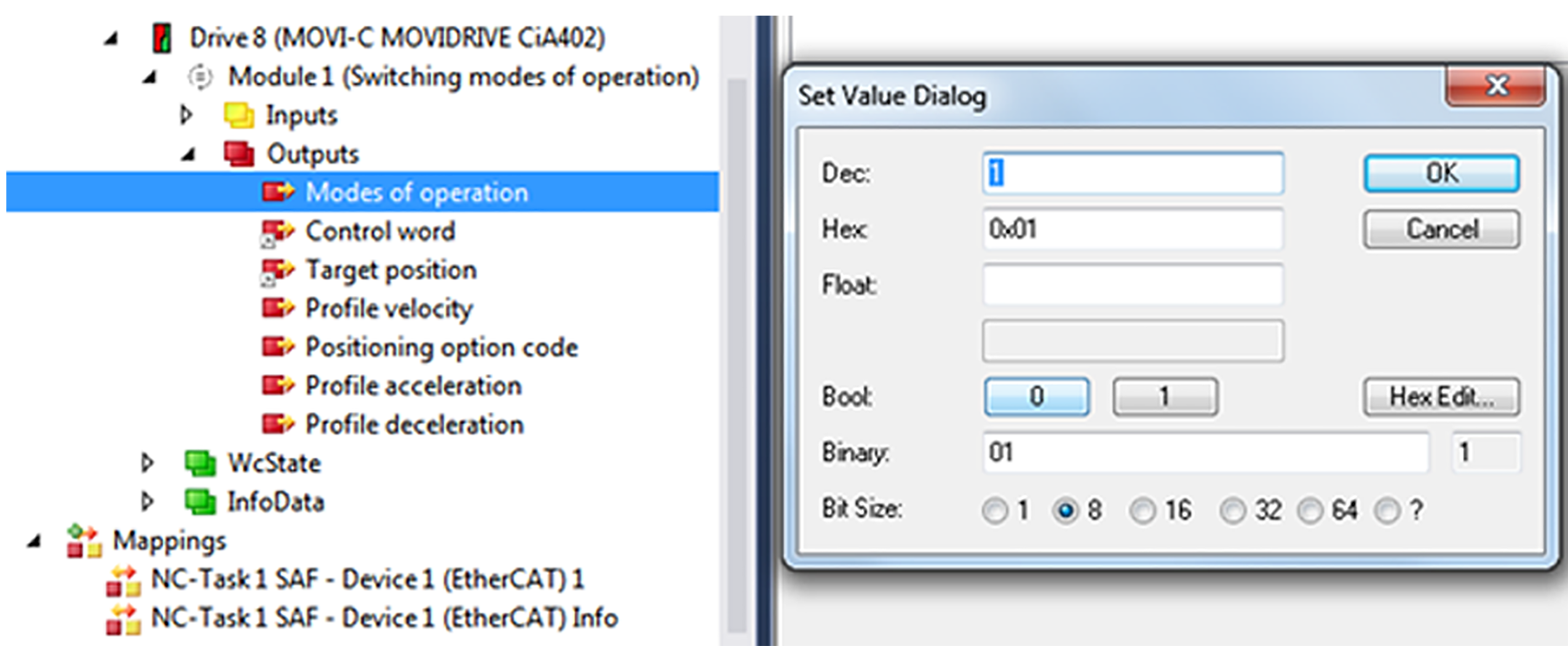
- Set pp in the "Modes of operation" process data object. Enter the value "1" in the editor window.
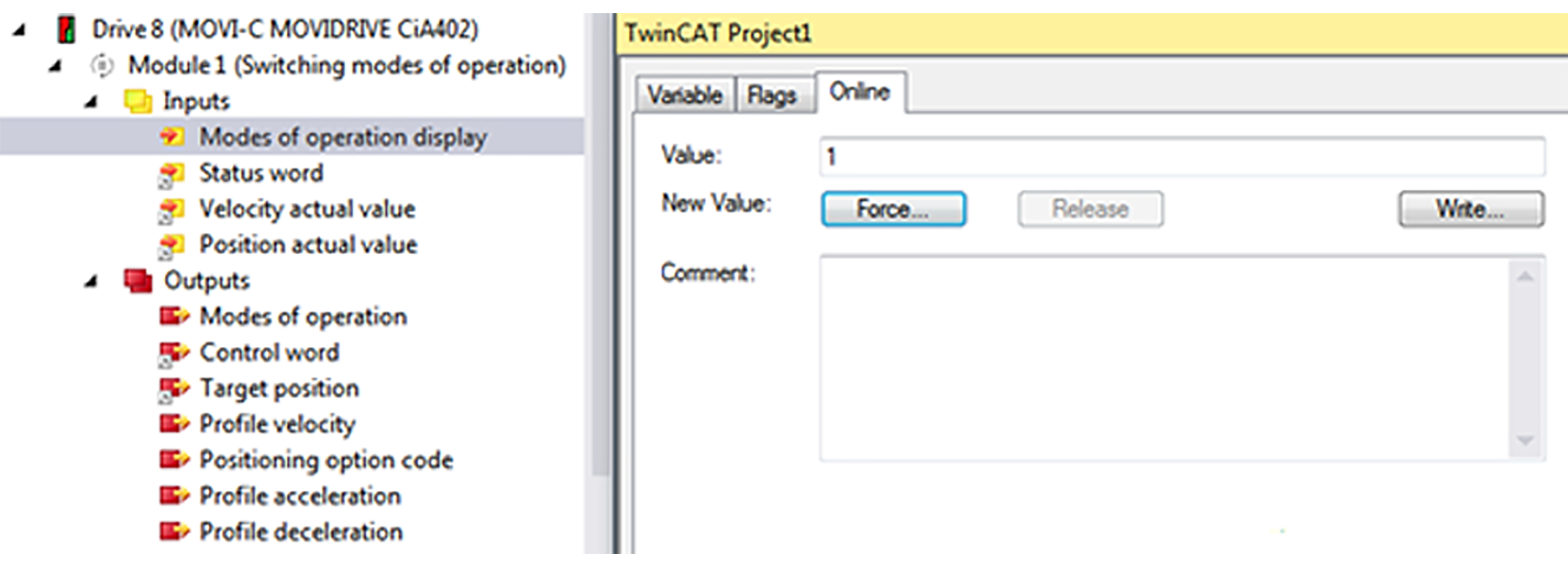
- The "Modes of operation display" process data object reports back the value "1".
- The value "24" is displayed on the display element of the inverter.
- If positioning has been performed successfully, the "Target reached" bit is reported in the status word ("Status word" process data object).
- A rising edge on bit 4 of the control word ("Control word" process data object) is necessary to accept a new position.
- Set the positioning type via the "Position option code" process data object. This setting is only active if control bits 5 and 6 of the control word are assigned accordingly.
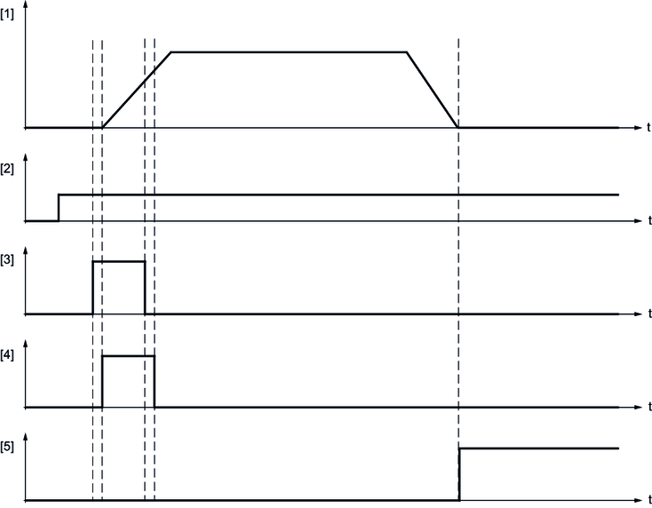
[1] | Actual speed |
[2] | Setpoint target position |
[3] | Control word: New setpoint (bit 4) |
[4] | Control word: Setpoint acceptance (bit 12) |
[5] | Status word: Target position reached (bit 10) |
Bit 6 | Bit 5 | Definition |
|---|---|---|
0 | 0 | Standard positioning Comparable to the positioning of the linear axis. If the "Min position range limit" (object 0x607B:2) and "Max position range limit" (object 0x607B:1) positioning limits are reached, the setpoint is automatically set to the other side of the limit. Positioning can be both relative and absolute. Positioning beyond the modulo limit values is only possible with this bit combination. |
0 | 1 | Positioning only in negative direction of movement If the setpoint position is greater than the actual position, the drive moves to the setpoint position via the "Min position limit" positioning limit (object 0x607B:1). |
1 | 0 | Positioning only in positive direction of movement If the setpoint position is less than the actual position, the drive moves to the setpoint position via the "Max position limit" positioning limit (object 0x607B:2). |
1 | 1 | Positioning by the shortest possible route to the setpoint position The direction of rotation of the drive is specified in such a way that the shortest distance results from positioning between actual position and current setpoint position. INFORMATION: If the distance between actual position and setpoint position is 180° in a 360° degrees system, the drive moves in positive direction. |
- Enter the following values in the editor window of the "Position option code" process data object.
Position option code | Value |
|---|---|
Standard positioning | 0 |
Only in negative direction | 64 |
Only in positive direction | 128 |
Shortest distance | 192 |
