Setting "Cyclic Synchronous Position" (csp) mode of operation
This mode of operation is used for position control. A position profile will therefore be calculated by the profile generator of the PLC and the position setpoints are sent cyclically (clock-synchronous) to the inverter. The inverter should follow these setpoints.
The following table shows the CiA402 objects which are required or recommended for the mode of operation. Not all objects must be located in the cyclic PDO image.
Note the maximum number of 8 entries in the cyclic PDO image (see Adapting the PDO image).
Control | Feedback | ||
|---|---|---|---|
Mode of operation | Mode of operation display | ||
Control word | Status word | ||
Target position | Position actual value | ||
Interpolation time period | Following error actual value (recommended) | ||
Proceed as follows:
- You have successfully started up the motor.
- You have integrated the inverter into the TwinCAT project via network scan or offline from the device catalog, linked it to a motion axis (see Motion axis: Integrating inverters) and transferred the corresponding process data object to the PDO image (see Adapting the PDO image).
- Set the reference units for distance (mm), angle (°), time (s), etc.
- Set the required user units. When doing this, pay attention to the gear unit ratio and ensure that the motor revolution remains CiA402-compliant (216 increments/revolution).
- Set the motion dynamics. To do this, specify the maximum speed and the up/down ramps.
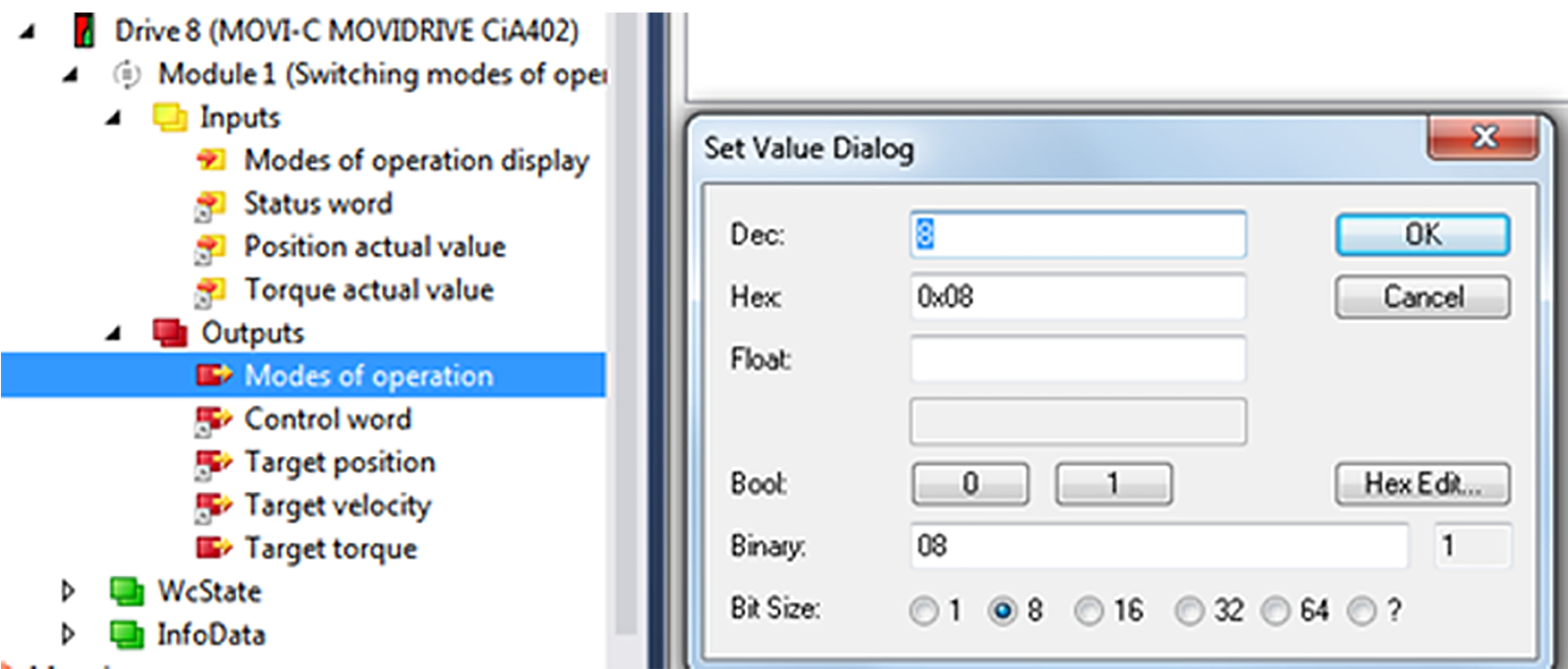
- Set csp in the "Modes of operation" process data object. Enter the value "8" in the editor window.
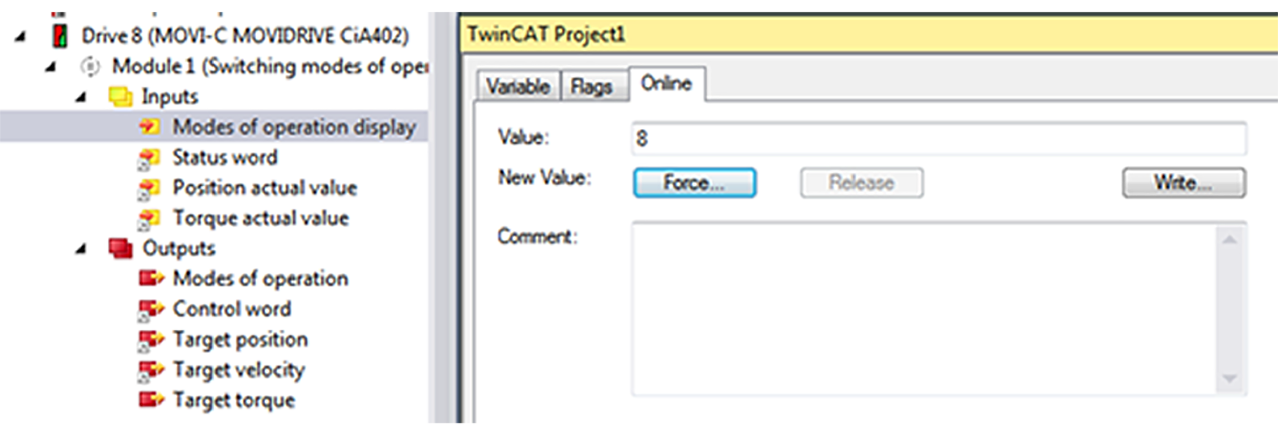
- The "Modes of operation display" process data object reports back the value "8".
- The value "16" will be displayed on the display element of the inverter.