Setting "Cyclic Synchronous Velocity" (csv) mode of operation
This mode of operation is used for positioning and speed control. A position profile is calculated by the profile generator of the PLC and the speed setpoints are sent cyclically (clock-synchronous) to the inverter.
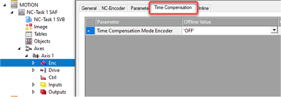
The current lag error must be calculated on the master because the drive is in speed mode. Please note that the "Position actual value", which is reported back by the drive, technically belongs to an earlier setpoint cycle due to interpolation. A dead time compensation must be performed in order to calculate the current lag error correctly. The dead time is typically between 3 and 4 setpoint cycles. In practical terms, 3.5 setpoint cycles have proven to be a sufficiently accurate approximation.
The following table shows the CiA402 objects which are required or recommended for the mode of operation. Not all objects must be located in the cyclic PDO image.
Note the maximum number of 8 entries in the cyclic PDO image (see Adapting the PDO image).
Control | Feedback | ||
|---|---|---|---|
Mode of operation | Mode of operation display | ||
Control word | Status word | ||
Target velocity | Position actual value | ||
Interpolation time period |
| ||
Proceed as follows:
- You have successfully started up the motor.
- You have integrated the inverter into the TwinCAT project via network scan or offline from the device catalog, linked it to a motion axis (see Motion axis: Integrating inverters) and transferred the corresponding process data object to the PDO image (see Adapting the PDO image).
- Set the reference units for distance (mm), angle (°), time (s), etc.
- Set the required user units. When doing this, pay attention to the gear unit ratio and ensure that the motor revolution remains CiA402-compliant (216 increments/revolution).
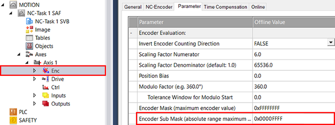
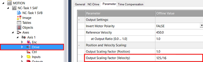
- Define settings for the encoder and the drive for the motion axis. To do this, open the "Parameters" tab on the respective configuration page and set the following values:
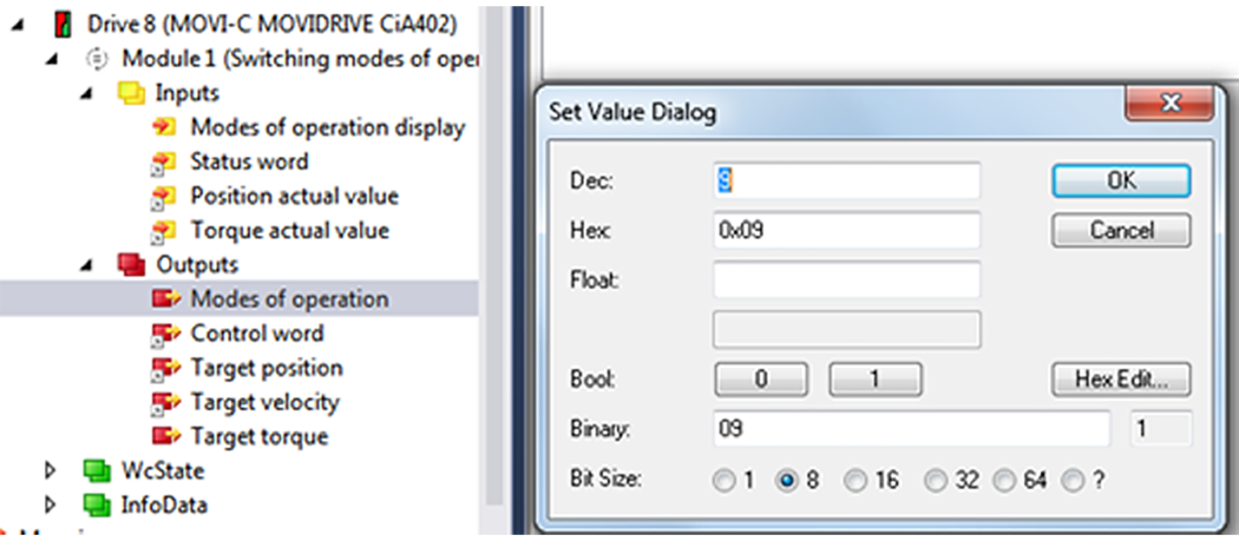
- Set csv in the "Modes of operation" process data object. Enter the value "9" in the editor window.
- Set the motion dynamics. To do this, specify the maximum speed and the up/down ramps.
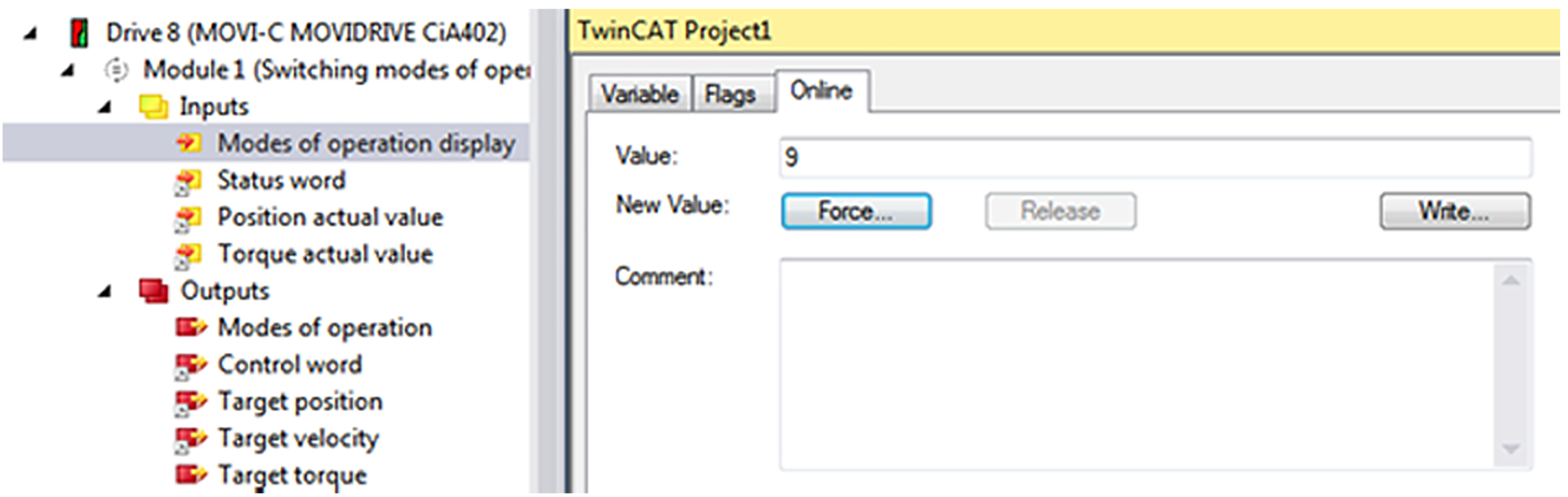
- The "Modes of operation display" process data object reports back the value "9".
- The value "15" is displayed on the display element of the inverter.