Speed filter
The speed filter can be parameterized with the SLS, SSM and SSR function. The speed filter makes it possible to exceed the speed limit "briefly" without triggering the error response. The speed filter is activated if the filter is > "0".
This additional functionality allows you to filter speed peaks in the event of an unbalanced operation (speed peaks in the signal). Starting from the difference between the current speed and the parameterized speed monitoring value, the distance integral is calculated and compared with the entered value. If the entered value is exceeded, the safety sub-function is triggered and the status of the safety sub-function changes from "1" to "0".
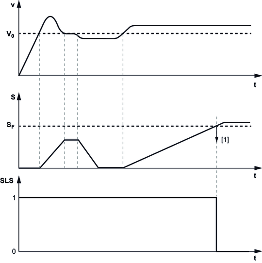
The following figure shows an example of the speed filter:

[1] | Response |
A drive exceeds the threshold "v0" parameterized in the SLS safety sub-function. When the threshold "v0" is exceeded, the speed above the threshold is integrated (S). If the current speed changes again to a value that is below the parameterized threshold "v0", the integral also decreases again to "0". The speed then rises again and remains above the parameterized threshold "v0". As a result, the integral increases again and, when the filter value (SF) is exceeded, triggers the corresponding response [1] (here: SLS safety sub-function). The status changes from "1" to "0". You can record the trend of the error value in the scope.
- SLS speed filter 8706.25 (offset 0 – 3)
- SSM speed filter 8706.31 (offset 0 – 1)
- SSR speed filter 8706.56 (offset 0 – 1)
For the initial startup of the speed filter, it is sensible to record the speed curve using the scope. In the first approximation, this maximum value can be used as the filter value for the speed filter, taking possible tolerances into consideration.