Pseudo closed loop
- The function module operates in "pseudo" closed-loop mode.
- The encoder signal is always evaluated at the end of a travel profile and a position correction is triggered via the profile generator.
- The encoder signal is taken into account by the controller.
- The setpoint for the current controller is generated by the higher-level profile generator.
- The actual position corresponds to the encoder value, normalized to position.
- An encoder value is output.
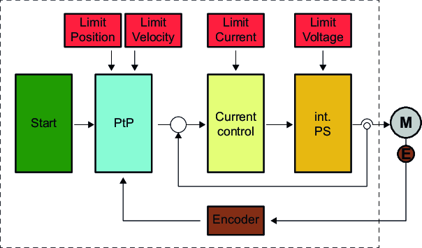
Structure
Start | Start parameter |
Limit Position | Position limiting |
Limit Voltage | Voltage limiting |
Position control | Position controller |
Current control | Current controller |
M | Motor |
Limit Velocity | Speed limitation |
Limit Current | Current limitation |
PtP | PtP position profile |
int. PS | Internal power stage |
Encoder | Actual encoder value |
Operating principle
In pseudo closed loop mode, the setpoint for the current controller is generated by the higher-level profile generator. The position and speed control loops are not closed and therefore the encoder signal is not evaluated in the control loops. In contrast to open loop, with pseudo closed loop the encoder signal is evaluated after the end of a profile operation and, if necessary, a position correction is triggered via the profile generator. The following objects are used with pseudo closed loop:
Pseudo closed loop | |
|---|---|
5: "Pseudo closed loop" setting | |
In the status word, "Target position reached" bit 10 is set if the deviation from the target position is smaller than the parameterized target window. | |
You can use this object to query the deviation between the setpoint and actual value. | |
You can use this object to specify a limit above which a warning will be issued via bit 8. | |
You can use this object to specify a limit above which an error will be output via bit 8. In addition, the module switches to the error state with positioning error 0x8611 in the event of an error. | |
Bit 12 in the status word remains set during the position correction. | |
0x8480-17 – Pseudo Closed Loop: Number of correction cycles | You can use this object to define the number of correction cycles. |
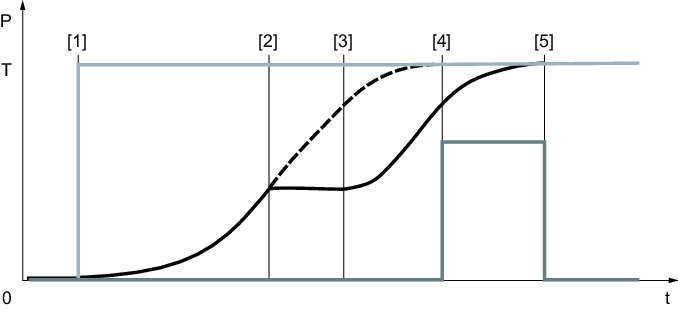
[P] | Actual position |
[T] | Setpoint position |
[t] | Time axis |
[1] | The first profile operation is started. The drive is enabled. |
[2] | Profile operation continues to run while the drive is blocked. |
[3] | Profile operation continues to run. The drive is unblocked. |
[4] | Profile operation is complete. Due to the high control deviation, the second profile operation is started. |
[5] | The actual position is equal to the setpoint position and the profile operation is ended. |
