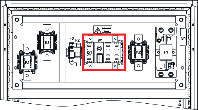
Replacing a defective Q1 disconnector
Part number | Designation | Tightening torque M8 |
|---|---|---|
29663334 | Disconnector DDC-200/2-SK | 14 Nm |
In the event of a defective Q1 disconnector, additionally check the following components for correct function:
- Auxiliary contacts Q1.1/Q1.2
- Fuse F1
- Fuse F2
- Fuse F3
- Contactor K1, K2, K3
- Storage bundle (are there defective modules in the storage bundle?)
Required tool:
- Hexagon socket: Set
- Wrench: Set
- Torque wrench 0 Nm – 20 Nm
Procedure:
- To ensure the correct installation depth of the linkage during reinstallation, mark the linkage.
- Remove the linkage by loosening the set screws.
- Loosen the M8 screws.
- Remove the auxiliary contacts.
- Remove all electrical connections.
- Remove the disconnector from the mounting plate.
- Mount the new disconnector on the mounting plate.
- Mount the auxiliary contacts.
- Restore all the electrical connections.
- Tighten the M8 screws to the specified torque.
- Mount the linkage.