End closing cover for DC link
The end closing covers prevent any contact with the DC link. Insert one end closing cover each on the first and last module of the axis system to close the through opening for the DC link busbar in the touch guard.
Each power supply module and the adapter bar sets are supplied with the required closing covers, see product manual > chapter Standard accessories and Available accessories.
The following figure shows an example of the procedure for inserting the end closing covers for the DC link into touch guards:
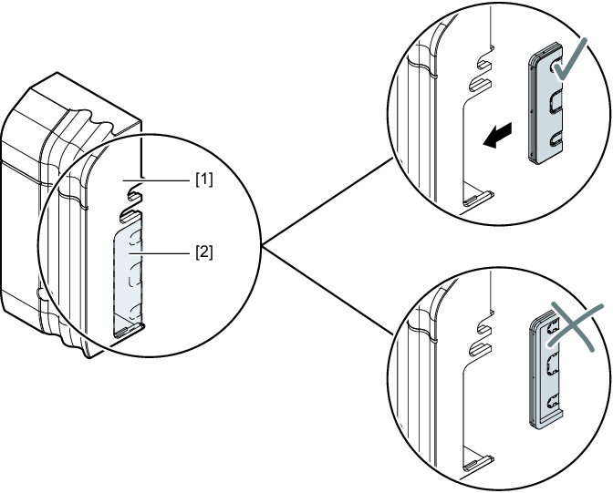
[1] | Touch guard |
[2] | End closing cover |
Proceed as follows:
- If the touch guard is still installed, remove it from the respective module, see chapter Removing the touch guard.
- Select the closing cover suitable for the respective module, see the following table.
- Insert the closing cover into the touch guard of the first and last module in the axis system.
- If no further work steps are required, install the touch guard on the respective module, see chapter Installing touch guard.
The following table shows the end closing cover required for the respective module:
Module | End closing cover left | End closing cover right |
|---|---|---|
MDP90A.. Sizes 1 – 4 |
| –As the module is never at the first or last position in the axis system, no end closing cover is required at this point. |
MDR90B.. | –As the module is never at the first or last position in the axis system, no end closing cover is required at this point. | –As the module is never at the first or last position in the axis system, no end closing cover is required at this point. |
MDR91B.. |
|
|
MDP92A.., MDE90A.., MDM90A.., MDF90B.., MDS90A.. |
|
|
MDA90A.. Sizes 1 – 5 MDD9.A.. Sizes 1 – 2 | –As the module is never at the first or last position in the axis system, no end closing cover is required at this point. |
|
MDA90A.. Size 6 | –As the module is never at the first or last position in the axis system, no end closing cover is required at this point. |
|