Transition closing cover for DC link
If a module with a narrow DC link busbar follows a module with a wide DC link busbar, the through opening for the DC link busbar in the touch guard may not be completely covered and degree of protection IP20 is not met. In this case, a transition closing cover must be inserted into the touch guard at this point. This way, the degree of protection IP20 is fulfilled. The transition closing cover is supplied with the adapter bar sets.
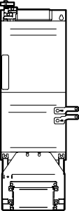
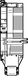
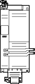
The following figure shows an example of the procedure for inserting the transition closing cover for DC link into the touch guards:
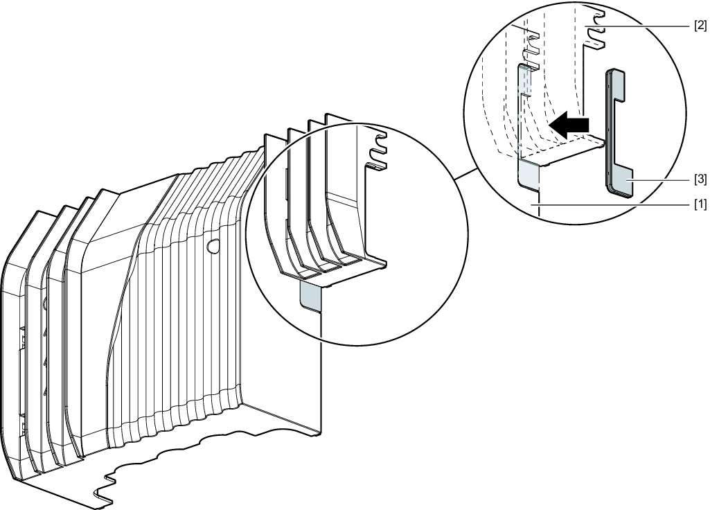
[1] | Touch guard of the module with "wide" design of the DC link busbar |
[2] | Touch guard of the module with "narrow" design of the DC link busbar |
[3] | Closing cover |
Proceed as follows:
- If the touch guard is still installed, remove it from the respective module, see chapter Removing the touch guard.
- Select the closing cover suitable for the respective module, see the following table.
- Insert the closing cover into the touch guard of the module with "wide" design of the DC link busbar.
- If no further work steps are required, install the touch guard on the respective module, see chapter Installing touch guard.
The following tables show which transition closing cover is required for which combination between the modules:
From module with "wide" design of | To module with "narrow" design | Transitional closing covers |
|---|---|---|
MDP90A.. Size 4 | MDA90A.. Size 1 – 2 |
|
|
|


From module with "narrow" design | To module with "wide" design | Transitional closing covers |
|---|---|---|
MDM90A.. | MDR91B.. |
|
|
|