Integrating the inverter into a POWERLINK network
The following device topology is used in the example:
- Higher-level controller (PLC) X20CP1585 from B&R Industrial Automation GmbH
- MOVIGEAR® performance mechatronic drive unit with electronics cover DFC40A..
- USM21A interface adapter
The startup of the other inverters in the MOVI‑C® modular automation system is performed in the same way.
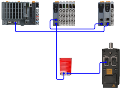
The following figure is a schematic representation of the device topology:

[1] | Supply voltage |
[2] | PLC |
[3] | Fieldbus connection |
[4] | MOVIGEAR® performance |
[5] | USB connection cable, type USB A‑B |
[6] | USM21A interface adapter |
[7] | Interface cable with RJ10/RJ10 connectors |
For configuration and startup of the devices, the following tools are used:
- Automation Studio from B&R Industrial Automation GmbH for the PLC
- MOVISUITE® for inverters from SEW‑EURODRIVE
Additional information
- Fieldbus stations in the sample project
- Integrating and configuring an inverter in the POWERLINK network
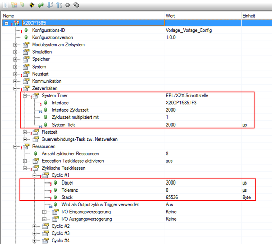
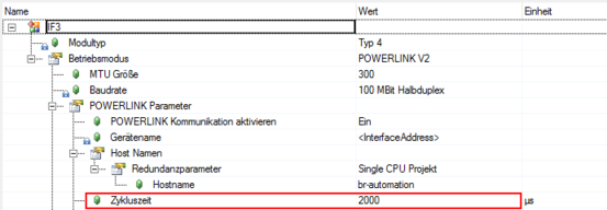
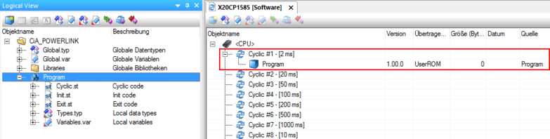
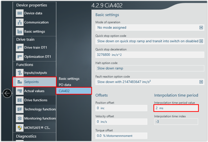
- Setting the interpolation time
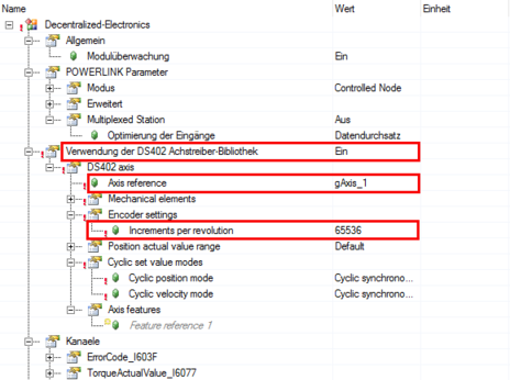
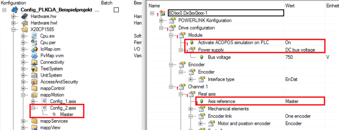
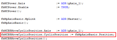
- Configuring inverter as CiA402 axis
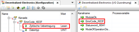
- Adapting the PDO image
- Setting "Profile Position" (pp) mode of operation
- Setting "Profile Velocity" (pv) mode of operation
- Setting "Cyclic Synchronous Position" (csp) and "Cyclic Synchronous Velocity" (csv) mode of operation
- Setting scaling