Setting the interpolation time
To prevent interpolation errors that lead to losses in control performance, the interpolation time in the PLC and in the inverter must match.
For MOVIGEAR® performance MGF..-DFC-C, an interpolation time of 2 ms and longer is possible.
Proceed as follows:
- You have mapped the POWERLINK network in an Automation Studio project.
- You have integrated the inverter into a MOVISUITE® project.
- In the System Designer, open the "Physical View" tab.
- Open the configuration of the PLC in the shortcut menu of the PLC and define the following settings:
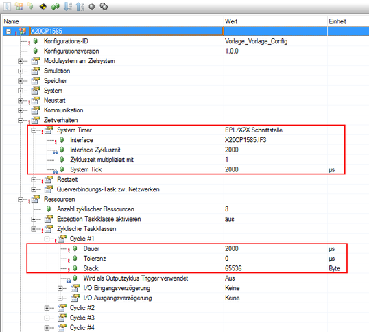
Parameter group | Parameter | Setting |
|---|---|---|
[Time Response] | System Timer | EPL/X2X interface |
[Time Response] > [System Timer] | Interface | X20CP1585.IF3 |
Interface cycle time | 2000Interpolation time of the inverter | |
Cycle time multiplied by | 1 | |
System tick | 20001) | |
[Resources] > [Cyclic Task Classes] > [Cyclic #x] | Duration | 20001) |
Tolerance | 0 | |
Stack | 65536 |
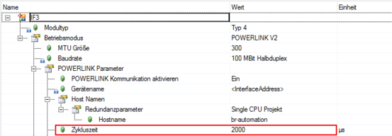
- Open the configuration of the interface on the "Physical View" tab in the shortcut menu of the POWERLINK interface "PLK" and also set the interpolation time of the inverter for the Cycle time parameter.
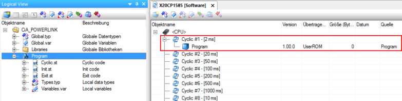
- To be able to control the inverter, insert a program into the project. To do this, switch to the "Logical View" tab and insert the program from the object catalog using drag-and-drop.
- The program is automatically assigned to a task class.
- Open the configuration of the software on the "Physical View" tab in the shortcut menu of the PLC.
- Use drag-and-drop to insert the program in the cycle class for which the interpolation time was also set.
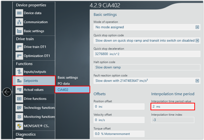
- Switch to the MOVISUITE® project.
- Open the configuration of the inverter and set the interpolation time. Make sure that you set the same value for the inverter as for the PLC in the Automation Studio project. If you change the interpolation time in the PLC, you must also change the interpolation time in the inverter.