Integrating and configuring an inverter in the POWERLINK network
The inverter must be added to an Automation Studio project, connected to the PLC, and configured.
During configuration, a node number is assigned to the inverter.
Proceed as follows:
- The address of the inverter is the address you have already set via the DIP switches of the drive unit (see chapter Setting the address).
- You have already downloaded the device description file (xdd file) of the inverter from the SEW‑EURODRIVE homepage (www.sew-eurodrive.com) and saved it locally on the engineering PC.
- Start the Automation Studio engineering tool and create a new Automation Studio project.
- Load the device description file into the project.
- Filter the hardware catalog for "third-party devices" and add the inverter ("Decentralized-Electronics" entry) to the System Designer using drag-and-drop.
- The interfaces of the devices are connected according to the device topology.
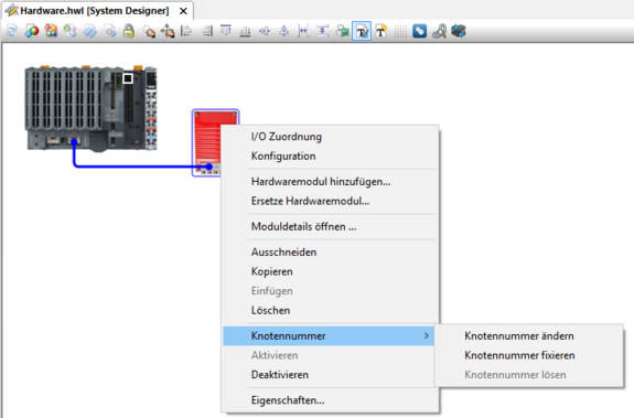
- Open the shortcut menu of the inverter with a right mouse-click and enter the node number of the inverter. The PLC addresses the inverter using this node number. The node number must match the address set in the inverter via DIP switches.
- Upload the project to the PLC. During initial startup, the operating system is also loaded into the PLC.
- If the PLC is in service mode after charging, you can display the current pending errors in the logger. Select the [Open] > [Logger] menu command to do this.
- If no errors are present, restart the PLC to have it enter Run mode.