Special case of POWERLINK master from B&R Industrial Automation GmbH: Connection via mailbox gateway
The connection of the engineering PC is explained in more detail using an example. The X20CP1585 higher-level controller from B&R Industrial Automation GmbH is used in the example. The MOVISUITE® engineering software and the Automation Studio tool are used for configuring and starting up the devices.
Proceed as follows:
- You have administrator rights on the engineering PC.
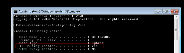
- Open the Windows prompt of the engineering PC with administrator rights and use the
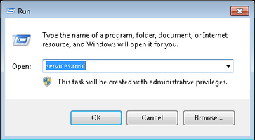
ipconfig/allcommand to check whether IP routing is activated or deactivated (default setting). - To activate IP routing, use the
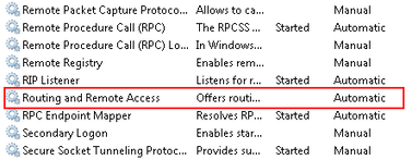
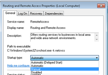
AusführenWindows function to open the "services.msc" services. - Open the shortcut menu of the
Routing und Remote Accessservice with a right mouse-click and call up the properties of the service. - Set the startup type to "Manual".
- Start the IP routing via the shortcut menu.
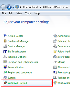
- To be able to transfer the MOVISUITE® data, you must enable the firewall ports
48898 Protokoll TCP incomingand48899 Protokoll UDP incomingon the engineering PC. To do this, open the firewall settings via the Windows Control Panel. - Start the Automation Studio engineering tool and create a new Automation Studio project.
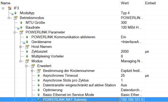
- Open the configuration of the interface on the "Physical View" tab in the shortcut menu of the "PLK" POWERLINK interface.
- In the "POWERLINK NAT Subnet" entry, the IP address of the POWERLINK interface is set to 192.168.101.0 by default.
- The IP addresses of a POWERLINK station is composed of the network address of the POWERLINK interface (here, the first 3 address blocks) and the node number. For example, the third station has the following IP address:
| Address |
|---|---|
IP address of the POWERLINK interface | 192.168.101.0 |
Node number of the POWERLINK station | 3 |
IP address of the POWERLINK station | 192.168.101.3 |
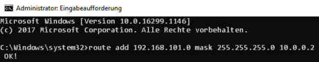
- Set a route so that the engineering PC can access the address range of the POWERLINK master. To do this, open the Windows prompt of the engineering PC with administrator rights and enter the following command:
route addIP address of the POWERLINK interfacemaskSubnet mask IP address of the POWERLINK master - In this example, the following addresses are assigned:
| Address |
|---|---|
IP address of the POWERLINK interface | 192.168.101.0 |
Subnet mask | 255.255.255.0 |
IP address of the POWERLINK master | 10.0.0.2 |
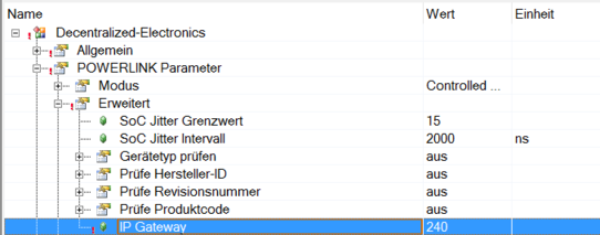
- The node number of the POWERLINK master is 240 by default. To enable the inverter to send telegrams to the POWERLINK master, enter the node number of the master into the configuration of the POWERLINK interface.
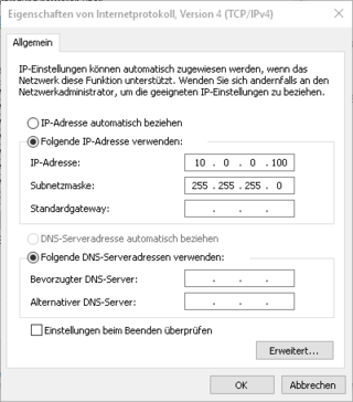
- In order for the engineering PC to communicate with the POWERLINK master, the network interfaces of the engineering PC and the POWERLINK master must be in the same network area. Note that the network address (here the first 3 address blocks) for all network stations must be identical and the station address (here the last address block) of the network stations must be different from one another. Configure the interface of the engineering PC accordingly.
- In this example, the following addresses are assigned:
| Address |
|---|---|
IP address of the POWERLINK master | 10.0.0.2 |
Subnet mask | 255.255.255.0 |
IP address of the engineering PC | 100.0.0.100 |
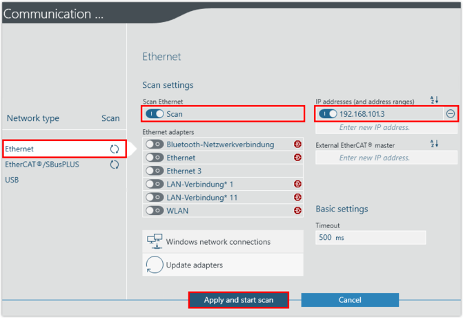
- Start MOVISUITE® and create a new project from a network scan.
- Select the network type (Ethernet) and enter the IP address of the inverter. Perform a network scan.