Synchronization mechanism with synchronous point
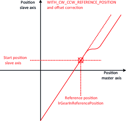
In the case of the previously mentioned synchronization mechanism, the "attachment point" of the lines results automatically during synchronization from the current positions of the master and slave axes or from the configured reference position IrGearInReferencePosition.
However, there are also scenarios, in which the definition of a new "attachment point" of the lines during synchronization is unwanted. This could be the case, for example, if a phase correction was made by means of an XOffsetCorrection or a amplitude correction was made by means of a YOffsetCorrection and this correction is intended to be retained for a subsequent synchronization. The following diagram illustrates this case.

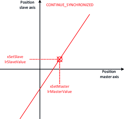
An offset correction causes a parallel shift of the lines. Upon subsequent synchronization, the user may not want to synchronize with the line defined by the reference position but instead with the line that resulted after the correction. In this case, the user can use a synchronization mechanism that synchronizes with the last synchronous point (eStartMode = "CONTINUE_SYNCHRONIZED").
As noted in the block diagram, the last synchronous point results from the combination of the two values "last master position" and "last slave position". These two values are saved internally. The user can specifically set the values and use them to control the "attachment point" of the lines during synchronization in any desired way. This makes this synchronization mechanism the most universally applicable.

When activating the synchronous operation (Gearing) operating mode, the current position of the master axis is evaluated. The "Adjust" alignment function can then be used to align the slave axis with the corresponding position on the lines. It is important in this case that synchronization and desynchronization occur without a transition, meaning in the idle state!

