Overview of operating modes
The software module MOVIKIT® Velocity Drive uses the speed control operating mode (200). The operating mode cannot be activated manually when using the MOVIKIT® Velocity Drive.
Operating modes of the MOVIKIT® Positioning Drive and their areas of application:
Operating mode | Decimal | Description |
|---|---|---|
Jog – position-controlled | 100 | Jog mode – position controlled (FCB 20) Encoder feedback required |
Jog – speed-controlled | 101 | Jog mode – speed controlled (FCB 05) Encoder feedback not required |
Speed | 200 | Speed control (FCB 05) Encoder feedback not required |
Reference travel – offset via parameter | 300 | Referencing with offset via parameter (FCB 12) |
Reference travel – offset via fieldbus | 301 | Referencing with offset via fieldbus (FCB 12) |
Absolute positioning
| 400 | Positioning absolute (FCB 09) |
Relative positioning | 401 | Positioning relative (FCB 09) |
Modulo positioning – positive direction | 402 | Positioning modulo – positive direction (FCB 09) |
Modulo positioning – negative direction | 403 | Positioning modulo – negative direction (FCB 09) |
Modulo positioning – optimized direction | 404 | Positioning modulo – optimized direction (FCB 09) |
Positioning absolute – Touchprobe remaining distance in direction of travel | 420 | Touchprobe positioning – absolute target position – remaining distance in direction of travel (FCB 09) |
Positioning absolute – Touchprobe remaining distance signed | 421 | Touchprobe positioning – absolute target position – remaining distance with sign (FCB 09) |
Positioning endless – Touchprobe remaining distance in direction of travel | 422 | Touchprobe positioning – endless – remaining distance in direction of travel (FCB 09) |
Positioning endless – Touchprobe remaining distance signed | 423 | Touchprobe positioning – endless – remaining distance with sign (FCB 09) |
Brake test – static | 700 | Brake test (FCB 21) Operating mode for the Brake test additional function |
INFORMATION

For operating function blocks, the configuration settings made in the MOVISUITE® configuration apply. Modulo operating modes can only be used if a cycle limit was set when configuring the software module under [Monitoring functions] > [Limit values].
INFORMATION
The behavior at standstill depends on the setting of the "Behavior at standstill" parameter (index 8563.1/8564.1).
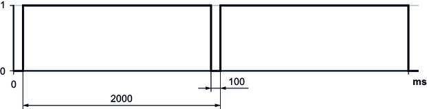
The following chapters provide a cycle diagram for each operating mode to help you better understand the operating principle. They also provide a process sequence with a description of the signals to be set and of the signal states.
- Requirements for cycle diagrams
- Switching operating modes
- Jog mode (100/101)
- Speed control (200)
- Referencing mode (300/301)
- Positioning – absolute (400)
- Positioning – relative (401)
- Modulo positioning – positive direction" (402)
- Modulo positioning – negative direction" (403)
- Modulo positioning – optimized direction" (404)
- Positioning absolute – Touchprobe remaining distance in direction of travel (420)
- Positioning absolute – Touchprobe remaining distance signed (421)
- Positioning endless – Touchprobe remaining distance in direction of travel (422)
- Positioning endless – Touchprobe remaining distance signed (423)