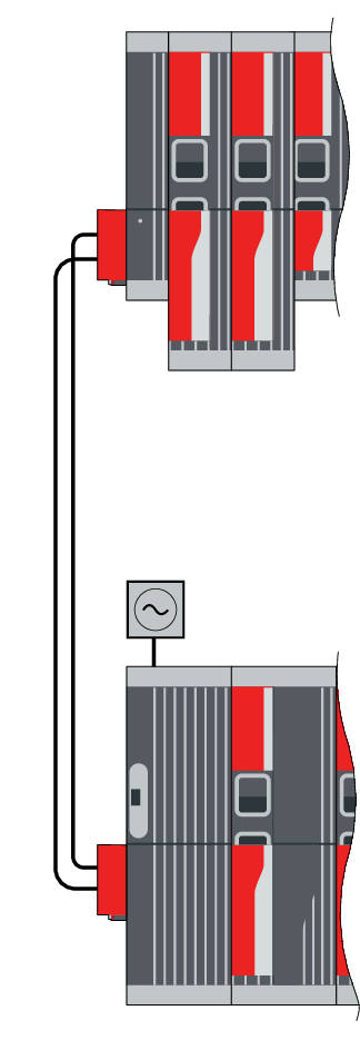
Setup variant 6
You can select this setup variant if the following specifications are met in the auxiliary row:
- There is a large distance < 50 m between the main row and the auxiliary row.
Applications in this setup must be tested by SEW-EURODRIVE for the individual application. Please contact SEW-EURODRIVE.
For the arrangement of the modules within a row, refer to chapter Power supply module selection.
| Auxiliary row |
|
- MDC90A.. (0001 – 0002) | Use is mandatory | |
- MDA90A.. (0020 – 0120) - MDD9.A.. (0020 – 0080) | Maximum of 8 modules | |
- MDA90A.. (0160 – 0240) | Maximum of 4 modules | |
- MDA90A.. (0320 – 0480) | Maximum of 2 modules | |
- MDS90A.. |
| |
- MDM90A |
| |
|
| |
Connection |
| |
Connection via cable lugs on DC link busbars or via connection units | ||
- Cable or conductor rail up to 50 m | ||
- Maximum cable cross section with cable lugs: 16 mm2 | ||
- Maximum cable cross section with connection units: 35 mm2 | ||
- Main row on the far left, MDR91B..: Set of connection units, part number: 28261674 (main row wide, auxiliary row narrow) | ||
- Main row on the far left, everything except MDR91B..: Set of connection units, part number: 28261666 (main row narrow, auxiliary row narrow) | ||
|
| |
Main row |
| |
- MDP90A.. (0250 – 1100) | ||
- MDR9.B.. (0500 – 0750) | ||
- MDF90A.. (0500 – 0750) |
| |
- MDP92A.. (0100 – 0250) | ||
- MDE90A.. (0200 – 0750) | ||
- MDA90A.. (0020 – 1800) |
| |
- MDC92A.. (0075 – 0125) | ||
- MDS90A.. | ||
- MDL91A.. | ||
- MDM90A | ||
When using MDC92A.., there are additional possible combinations.
Check the following measures depending on the system constellation:
- Use of DC link chokes in the connection from the main row to the auxiliary row
- Adapted regulator settings in the CFC control mode
