Configuring the EtherCAT® Master for data transmission
In order for the engineering PC to communicate with the EtherCAT® master, the network interface of the engineering PC and the engineering interface of the EtherCAT® master must be in the same network area.
Note that the network address (here the first 3 address blocks) for all network stations must be identical and the station address (here the last address block) of the network stations must be different from one another.
The following example deals with case 2: MOVISUITE® and EtherCAT® master on different device hardware. Settings that are also relevant for case 1 are marked.
Example:
Device | IP address | Subnet mask | Standard gateway |
|---|---|---|---|
Engineering PC | 192.168.20.10 | 255.255.255.0 | Optional |
EtherCAT® master | 192.168.20.2 | 255.255.255.0 | Optional |
Proceed as follows:
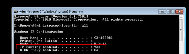
- Open the Windows entry prompt for the EtherCAT® master with administrator authorization and utilize the
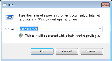
ipconfig/allcommand to inspect whether IP routing is activated or deactivated (default setting). - To activate IP routing, use the
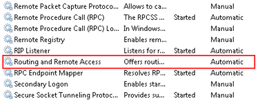
AusführenWindows function to open the "services.msc" services. - Open the shortcut menu of the
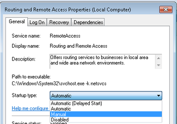
Routing und Remote Accessservice with a right mouse-click and call up the properties of the service. - Set the startup type to "Manual".
- Start the IP routing via the shortcut menu.
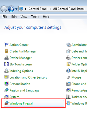
- To be able to transfer the MOVISUITE® data, you must enable the firewall ports
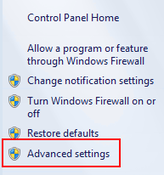
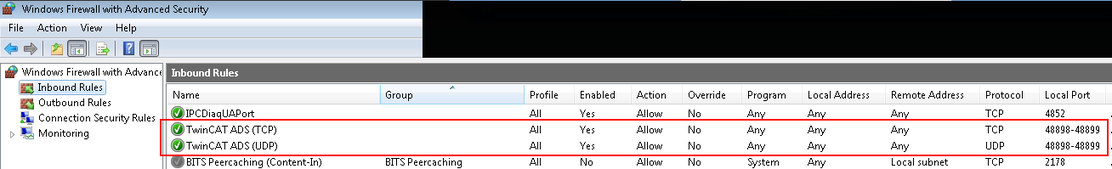
48898 Protokoll TCP incomingand48899 Protokoll UDP incomingon the engineering PC. To do this, open the firewall settings via the Windows Control Panel. - Select the [Advanced Settings] menu command and open the rules for incoming and outgoing protocols.
- Use the shortcut menu to activate both ports.
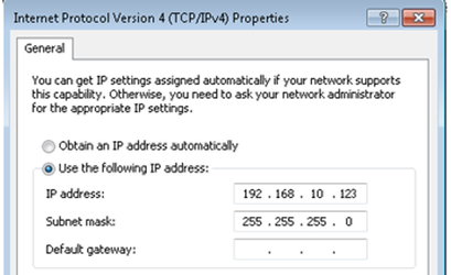
- If you continue an EtherCAT® phase via an EtherCAT® connection from Beckhoff Automation GmbH (EK1110), the TwinCAT 3 engineering tool automatically creates a virtual Ethernet adapter in the "RUN" operating mode. Assign the adapter an IP address from the subnet mask of the mailbox gateway.
- In this example, the virtual Ethernet adapter has been assigned the IP address 192.168.10.123. The IP address of the mailbox gateway is 192.168.10.254.
- The virtual Ethernet adapter only becomes visible in the "Configuration" operating mode when a functioning TwinCAT configuration is loaded.
- If you use a real network adapter, set the IP address in the "Configuration" operating mode.
- The engineering PC is now enabled for the data transmission.
