Example
The following example shows step-by-step how the position of a workpiece can be measured using the P1_OnXAxis_P2_OnXAxis_XGreaterThanP1_P3_OnYAxis_Ypositive and Touchprobe-Measure method.
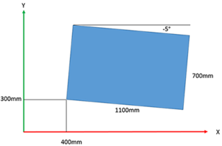
- The workpiece with the dimensions 1100 mm x 700 mm is rotated -5° about the Z-axis with respect to the BASE coordinate system. The bottom left vertex has the coordinates X = 400 mm, Y = 300 mm
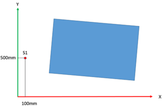
- First, the robot is moved to any starting point S1 to the left of the workpiece.
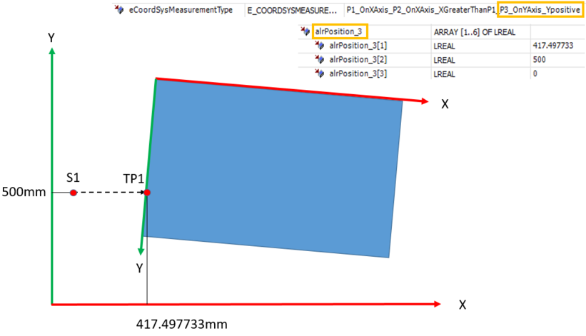
- Now, a movement in positive X-direction takes place with activated Touchprobe-Measure. The Touchprobe position TP1 is assigned to the alrPosition_3 input variable, because the point in the example lies on the Y-axis of the coordinate system to be measured.
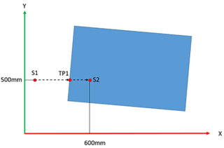
- The robot is then moved to any point S2 on the workpiece.
- Now, a movement in positive Y-direction takes place with activated Touchprobe-Measure. The Touchprobe position TP2 is assigned to the alrPosition_1 input variable, because the point in the example lies on the X-axis of the coordinate system to be measured.
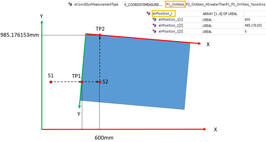
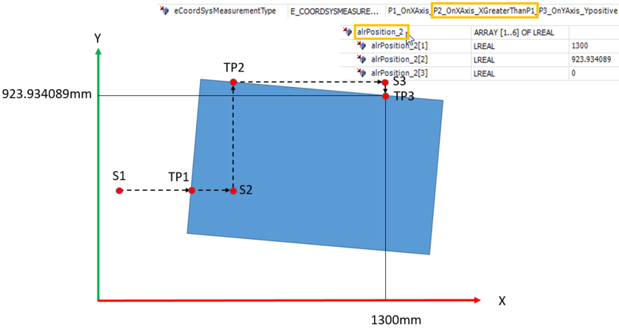
- The robot is then moved in the positive X-direction to any point S3 above the workpiece.
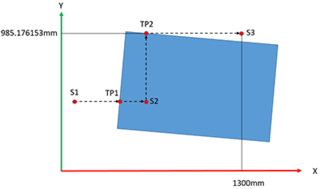
- Now, a movement in negative Y-direction takes place with activated Touchprobe-Measure. The Touchprobe position TP3 is assigned to the alrPosition_2 input variable, because the point in the example lies on the X-axis of the coordinate system to be measured with a larger X-coordinate than for point TP2. If no Touchprobe trigger occurs during movement in the negative Y-direction, because the workpiece is rotated counterclockwise about the Z-axis relative to BASE, for example, then another measuring run in the positive Y-direction would be required in the example.
- When the ComputeTransform method is executed, the position of the coordinate system to be measured is output, the origin of which is placed in the top left corner. Here, the input variable is alrAdditionalTransform = (0, 0, 0, 0, 0, 0).
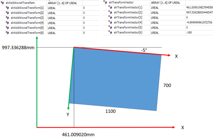
- If the origin of the coordinate system to be measured should be placed in the lower left corner, for example, with the Z-axis pointing in the same direction as the Z-axis of the BASE coordinate system, the alrAdditionalTransform additional transformation can be used as shown, so that now, rounded due to measuring inaccuracies, the coordinates of the coordinate system to be measured X = 400 mm and Y = 300 mm are also output, as initially assumed.
- As an alternative to the procedure described above, points TP2 and TP3 could also be measured directly on the lower edge of the workpiece instead of on the upper edge. Then, the additional transformation would be unnecessary. Accordingly, numerous other processes are also conceivable, depending on the possibilities in the concrete application and the desired position of the coordinate system to be measured.
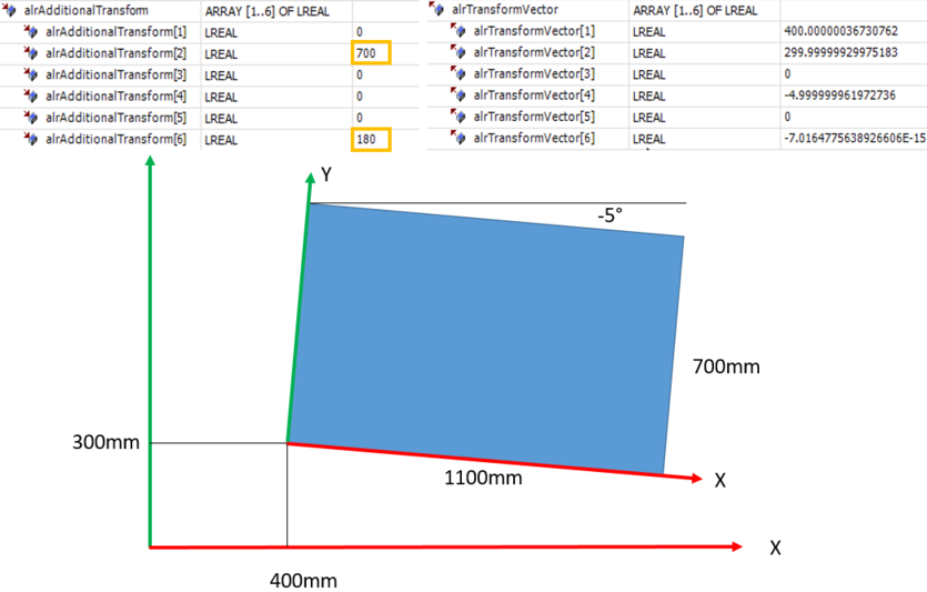
- The resulting alrTransformVector transformation can be used, for example, directly in the SetTransform method of a static coordinate system:
fbStaticTransform.SetTransform(fbCoordSysMeasurement.alrTransformVector);
