Winding axis to linear joint
With this type of crank, the motion of a rotary single axis is transferred to the motion of a linear joint axis. In particular, a belt is wound on top of each other on the single axis, for example, so that the effective diameter of the rotary single axis changes during rotation.
|
Example
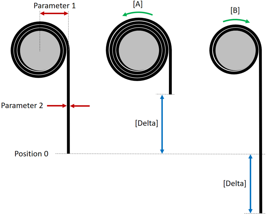
In the example shown, the zero position of the axis is depicted on the left, with parameter 1 as the effective radius in this position and parameter 2 as the thickness of the winding material.
In case [A], the effective radius increases in positive rotation (green arrow). The positive direction of movement of the linear joint axis points upwards in the case shown in the figure.
In case [B], the effective radius decreases in positive rotation (green arrow). The positive direction of movement of the linear joint axis points downwards in the case shown in the figure.
Parameterization
Parameter | Description |
|---|---|
Cranks | |
Single axis | Index of single axis and joint axis between which the crank operates (for the 1st axis, the value 1 must be entered). |
Parameter 1 | Only used if parameter 8 = 0 or 1 Effective radius of the rotary single axis in the zero position of the axis |
Parameter 2 | Only used if parameter 8 = 0 Thickness of the wound material
|
Parameters 3..7 | Partially used if parameter 8 ≠ 0 |
Parameter 8 | Identification of the input of parameters |
Startup
The rotary single axis must be configured with the unit degrees [°] in the drive train (although a linear joint axis of the selected kinematic model is actuated). The rotary single axis is converted into a linear joint axis by the crank.
The software limit switches must be set in such a way that the winding material is not unwound further than mechanically possible. For correct function of the software limit switches of the joint axes and the Cartesian axes in the software module, the parameters must be set correctly according to the following description.
If the required parameters 1 and 2 are known, they are simply entered. The value "0" must be entered in parameter 8 for this purpose.
However, if there are uncertainties and high accuracy is desired (especially to account for elongation and reduction in thickness of the winding material under load), the crank can be measured in several ways according to the procedures described below. In all variants, you can read out the effectively used parameter 1 (effective radius in zero position) and parameter 2 (thickness of wound material) for diagnostic purposes after updating the configuration data and starting the MOVI-C® CONTROLLER in the IEC Editor ("MyRobot" corresponds to the name of the robot node issued by the user in MOVISUITE®):
SEW_GVL_Internal.MyRobot.fbAxisJointTransformation.
stOut.stConfig.astCrank[Index].alrPar[1 bzw. 2]
