Default values
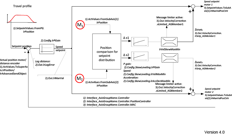
The schematic diagram below shows how the default values work:

- The profile generator of the axis group specifies a position setpoint. The position setpoint is compared to the current position of the motor encoder or the external encoder and forms the lag error for the axis group.
- This lag error is transferred to the position controller of the axis group, which specifies the speed setpoint for the individual axis group member.
- The software module compares the positions of the individual axis group members. If the position does not correspond, a speed correction value is applied to the axis group member. In addition, this value can be kept to a realistic level using a limiter.
- The sum of the speed setpoint and the speed correction value is transferred to the axis group member.
