Using the relay output for additional functions 7, 9, 12 and 13

WARNING

Risk of crushing if the drive starts up unintentionally.
Severe or fatal injuries.
- The brake coil must match the line voltage (e.g. 400 V).
- Do not assign port X1:14.
- One of the additional functions 7, 9,12, or 13 must be activated, otherwise the brake is released permanently. Be sure to keep this in mind when replacing the MOVIMOT® inverter. If none of these functions is activated, relay contact K1 acts as ready signal contact. This means that the brake is released even without enable when using the BGM option.
The following figure shows the use of relay contact K1 for controlling the mechanical brake with the BGM brake rectifier.
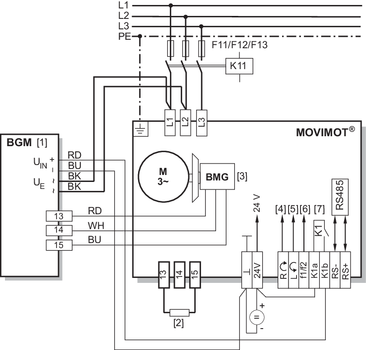
[1] | BGM brake control mounted in the connection box |
[2] | BW external braking resistor (assignment see chapter "Technical data") |
[3] | DC 24 V supply |
[4] | Clockwise/stop |
[5] | Counterclockwise/stop, observe direction of rotation, see chapter Connection of MOVIMOT® drive |
[6] | Setpoint changeover f1/f2 |
[7] | Brake relay |
