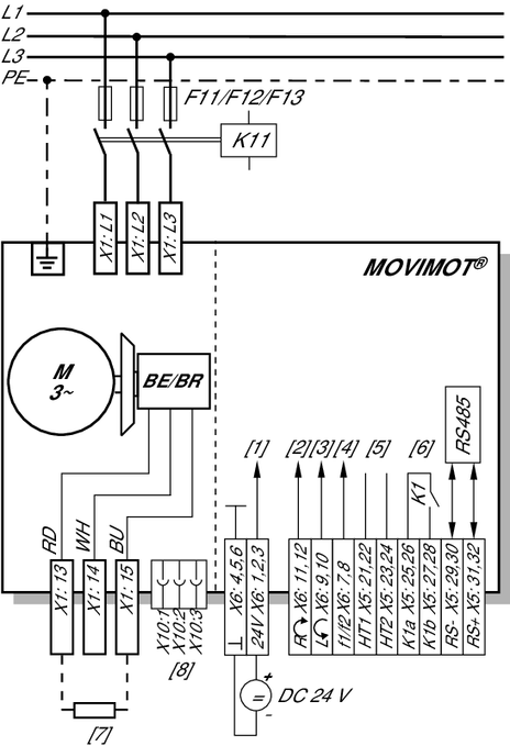
Connection of MOVIMOT® drive
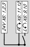
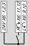
| Functions of the CW/stop and CCW/stop terminals in binary control mode: | |||
Direction of rotation |
Direction of rotation | |||
Functions of terminals f1/f2: | ||||
|
| |||
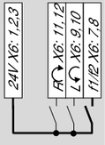
Functions of the CW/stop and CCW/stop terminals with control via RS485 interface/fieldbus: | ||||
| Both directions of rotation | |||
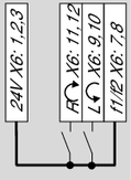
[1] | DC 24 V supply (external or MLU..A/MLG..A options) |
| Only CW Setpoint input for CCW rotation will stop the drive. | |
[2] | CW/stop (binary input) | |||
[3] | CCW/stop (binary input) | |||
[4] | Setpoint changeover f1 / f2 (binary input) |
| Only CCW Setpoint specifications for CW direction of rotation cause the | |
[5] | HT1/HT2: Intermediate terminals for specific wiring diagrams | |||
[6] | Ready signal (contact closed = ready for operation) | |||
[7] | BW.. braking resistor (only for MOVIMOT® drives without mechanical brake) |
| Drive is blocked | |
[8] | Connector for connecting the | |||