External safety controller requirements
You can also use a safety relay as an alternative to a safety controller. The following requirements apply mutatis mutandis.
- For safety-relevant applications up to Performance Level d according to EN ISO 13849-1, the safety controller and all other safety-related subsystems must be approved for at least Performance Level d according to EN ISO 13849‑1 or SIL 2 according to EN 61508. To determine the performance level of the overall application, you can use the method described in EN ISO 13849-1 to combine several safety-related subsystems (without a PFH‑value calculation). However, SEW‑EURODRIVE recommends determining the PFH value for the overall application. The PFH value for MOVIMOT® MM..D is 0 1/h (fault exclusion).
- For safety-related applications up to SIL 2 according to EN 62061, the safety controller and all other safety-related subsystems must be approved for at least SIL 2 according to EN 61508 or Performance Level d according to EN ISO 13849-1. You must also determine the probability of a dangerous failure per hour (PFH value). To determine the PFH value for the overall application, the PFH value for MOVIMOT® = 0 1/h (fault exclusion).
Application | Requirement for safety controller |
|---|---|
Performance level d according to EN ISO 13849-1 | Performance level d according to EN ISO 13849-1 SIL 2 according to EN 61508 |
SIL 2 according to EN 62061 | Performance level d according to EN ISO 13849-1 SIL 2 according to EN 61508 |
- The wiring of the safety controller must be suitable for the endeavored safety class (see manufacturer's documentation). Safety circuits with MOVIMOT® MM..D require 2-pole disconnection.
- You must strictly adhere to the values specified for the safety controller when designing the circuit.
- The switching capacity of the safety relays or the relay outputs of the safety controller must correspond at least to the maximum permitted, limited output current of the 24 V voltage supply.
- Observe the manufacturer's instructions concerning the permitted contact loads and fusing that may be required for the safety contacts. If the manufacturer provides no specific information, the contacts must be protected with 0.6 times the nominal value of the maximum contact rating specified by the manufacturer.
- To ensure protection against unintended restart in accordance with DIN EN ISO 14118, the safety controllers must be configured and connected in such a way that resetting the command device alone does not lead to a restart. Restart is only permitted after a manual reset of the safety circuit.
- The 24 V power supply input of MOVIMOT® inverter comes equipped with a serial polarity protection diode as well as a buffer capacitor with C = 120 µF. This must be considered as load when dimensioning the switching output.
"Safety relay" switching example
The following figure shows the basic connection of an external safety relay (according to the requirements listed above) to the MOVIMOT® MM..D drive. Observe the information in the respective manufacturer data sheets when connecting.
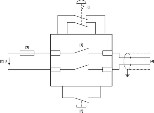
[1] | Safety relay with approval |
[2] | DC 24 V voltage supply |
[3] | Fuses according to the manufacturer's specifications for the safety relay |
[4] | Safety-related DC 24 V voltage supply |
[5] | Reset button for manual reset |
[6] | Approved emergency stop actuating device |
