Interconnection
The following figure shows an example of the interconnection of the main components of a protection concept with a circuit breaker. The contactors shown must be controlled via a coupling relay.
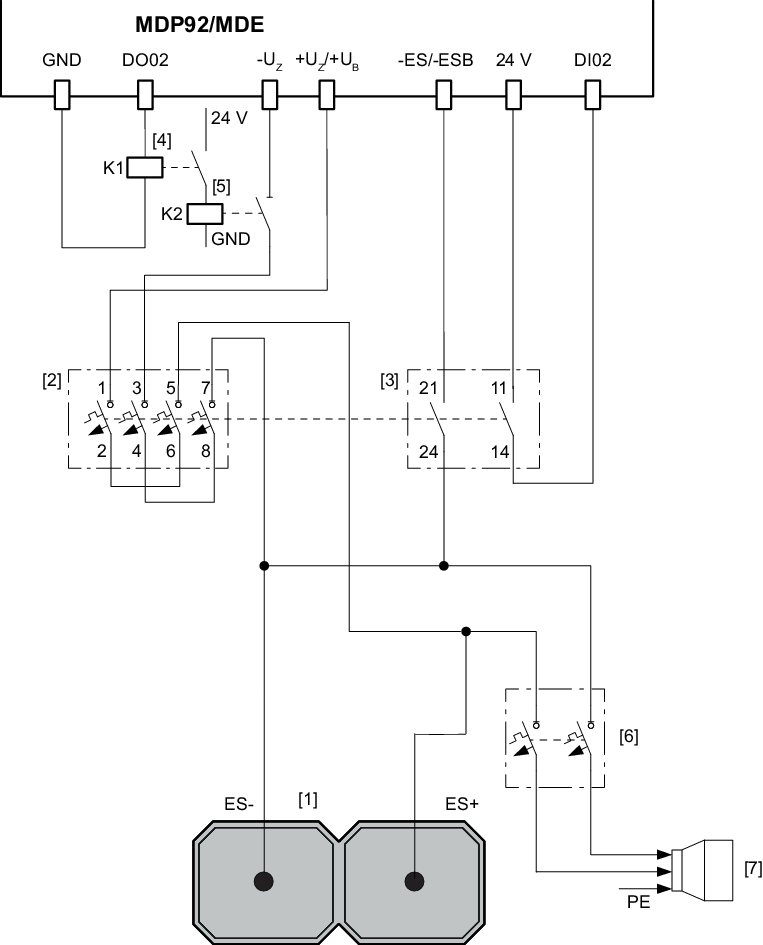
[1] | Energy storage modules |
[2] | Circuit breaker |
[3] | Circuit breaker auxiliary contacts |
[4] | Coupling relay K1 for synchronizing contactor K2 |
[5] | Synchronizing contactor K2 |
[6] | Discharge fuse |
[7] | Discharge connection socket |
INFORMATION

Other digital inputs/outputs can also be used instead of DI02 and DO02. Adjust the parameterization accordingly.
Interconnection with fuse
The following figure shows an example of the interconnection of the main components of a protection concept without a circuit breaker. The contactors shown must be controlled via a coupling relay.
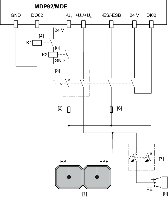
[1] | Energy storage modules |
[2] | Main fuse |
[3] | Switch disconnector (optional) |
[4] | Coupling relay K1 for synchronizing contactor K2 |
[5] | Synchronizing contactor K2 |
[6] | Measuring channel fuse |
[7] | Discharge fuse |
[8] | Discharge connection socket |
INFORMATION
Other digital inputs/outputs can also be used instead of DI02 and DO02. Adjust the parameterization accordingly.
Implement the interconnection according to the protection concept suitable for your application.
The following table shows the connection from the connection cables to the terminals of the MOVIDRIVE® modular MDP92A-.. power supply module or the MDE90A-. DC/DC converter module:
Connection | MOVIDRIVE® modular | |||
|---|---|---|---|---|
MDP92A-0100.. | MDP92A-0250.. | MDE90A-0200.. | MDE90A-0750.. | |
GND | X20:11 | X20:11 | X20:11 | X20:11 |
DO02 (binary output 2) | X20:5 | X20:5 | X20:5 | X20:5 |
-UZ | X12:2 | X4_B | X12:2 | X13 |
+UZ/+UB | X12:1 | X4_B | X12.3 | X13 |
-ES/-ESB | X12:6 | X1:2 | X12:5 | X12:3 |
DC 24 V | X20:1 | X20:1 | X20:1 | X20:1 |
DI02 (binary input 2) | X20:8 | X20:8 | X20:8 | X20:8 |
If an energy storage module of type MDC92A-0125.. is present, you can alternatively use the –UZ and +UZ power terminals on X4_B of the energy storage module to connect the power cable.
The connection cable between the measuring channel fuse and the MOVI-DPS® storage unit must be short-circuit-proof and ground-fault-proof. The maximum cable length is not specified.
