MDP90A.. power supply module Size 1, 1A
The following 3 connections exist:
Circuit 1 | Circuit 2 | Circuit 3 |
|---|---|---|
|
|
|
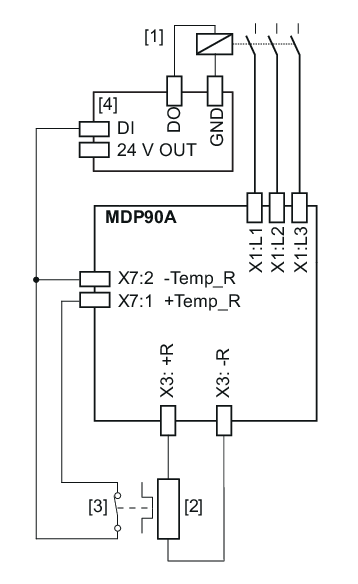
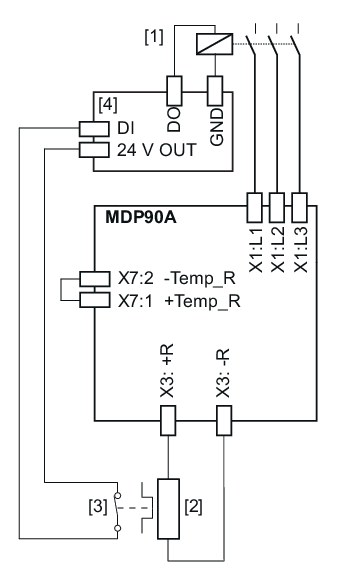
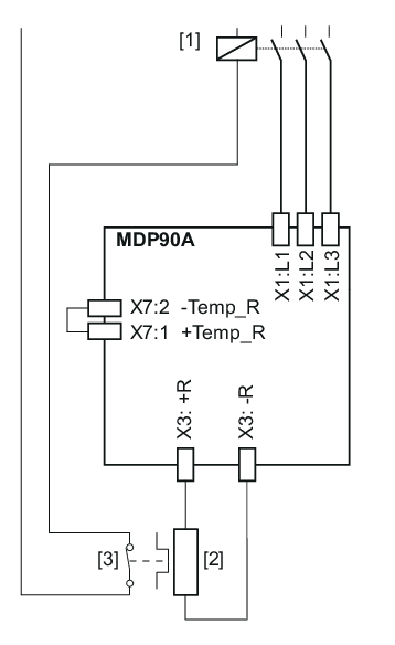
[1] | Line contactor | [2] | Braking resistance | [3] | Internal temperature switch | [4] | PLC |
Connection 1
INFORMATION

When connection 1 is used, the reference potential GND of the digital inputs of the PLC must be the same as the reference potential of the power supply module.
The signal contact is evaluated in the power supply module and in the PLC.
If the internal temperature switch responds, note the following:
- The PLC must disconnect the power supply at all poles.
- The power supply module switches all axis modules to "Output stage inhibit".
Connection 2
The signal contact is only evaluated in the PLC.
If the internal temperature switch responds, note the following:
- The PLC must disconnect the power supply at all poles.
- After disconnecting the power supply, the axis modules respond to line phase failure according to the parameterized response.
With circuit 2, it is possible that the PLC finishes the current travel cycle although the thermal circuit breaker has tripped. Only then is the power supply disconnected. In this case, the residual braking energy Wres = PBR_nom × 20 s must not be exceeded.
Connection 3
The signal contact directly affects the line contactor.
If the internal temperature switch responds, note the following:
- A response by the PLC is not required.
- After disconnecting the power supply, the axis modules respond to line phase failure according to the parameterized response.
If the braking resistor has internal thermal protection (e.g. BW100-002), a line contactor is not necessary. A response by the PLC is not required. X7:1 is jumpered with X7:2.
