MDP90A.. power supply module size 2 – 4 and MDR9.B..
The following 3 connections exist:
Circuit 1 | Circuit 2 | Circuit 3 |
|---|---|---|
|
|
|
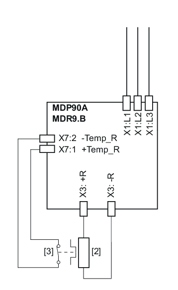
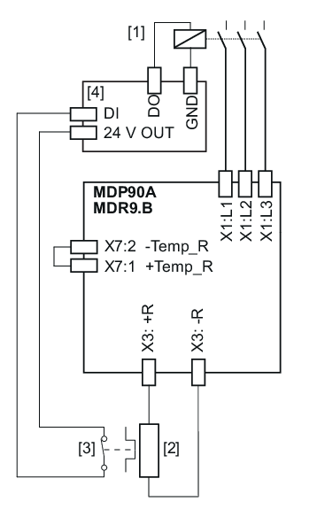
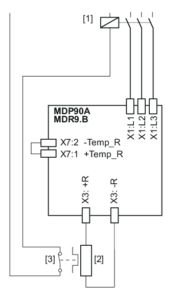
[1] | Line contactor | [2] | Braking resistance | [3] | Internal temperature switch | [4] | PLC |
Connection 1
INFORMATION

When using connection variant 1 (connection of power supply module without line contactor), the power supply module must be supplied with external DC 24 V. If the MDS90A.. switched-mode power supply module is used, it must be connected to the AC supply. The AC supply must be permanently present, therefore SEW-EURODRIVE recommends monitoring the AC supply. If the MDS90A switched-mode power supply module is used, the "AC-Available" signal is available for it.
The signal contact is evaluated in the power supply module.
If the internal temperature switch responds, note the following:
- A response by the PLC is not required.
- It is not necessary to disconnect the line connection using an external switching device.
- The power supply module switches all axis modules to "Output stage inhibit".
Connection 2
The signal contact is only evaluated in the PLC.
If the internal temperature switch responds, note the following:
- The PLC must disconnect the power supply.
- After disconnecting the power supply, the axis modules respond to line phase failure according to the parameterized response.
With circuit 2, it is possible that the PLC finishes the current travel cycle although the thermal circuit breaker has tripped. Only then is the power supply disconnected. In this case, the residual braking energy Wres = PBR_nom × 20 s must not be exceeded.
Connection 3
The signal contact directly affects the line contactor.
If the internal temperature switch responds, note the following:
- A response by the PLC is not required.
- After disconnecting the power supply, the axis modules respond to line phase failure according to the parameterized response.
