Feeding in/feeding out (600/601)
INFORMATION

Monitoring of the software limit switches is deactivated in operation without an encoder.
Use hardware limit switches to monitor the travel range.
The following figure shows a typical application example of the "rapid/creep speed positioning" principle.

In this roller conveyor, longer tracks are divided into segments.
Decentralization of positioning relieves the central controller. The independence of bus runtimes enables high positioning accuracy. This allows for a rapid segment-by-segment change of the goods.
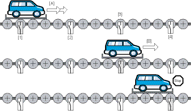
[1] | Sensor "stop CCW" | [A] | Rapid movement |
[2] | Sensor "F/SF/S = Rapid/creep speed | [B] | Slow movement |
[3] | Sensor "F/S1) CW" | ||
[4] | Sensor "stop CW" |
Operating mode "Feed-in"
Functional description | |
|---|---|
Mode selection | Mode 600 |
Prerequisite | The drive is enabled. |
Functional | The direction of rotation is selected via PO 1:4 or PO 1:5. At the positive edge of the start bit, the drive accelerates along the set acceleration ramp until it reaches rapid speed. Upon tripping of the "rapid/creep speed" sensor, the drive brakes along the set deceleration ramp until it reaches creep speed. After the "Stop" sensor trips, the drive brakes with the stop deceleration (PO 8 or fixed setpoint) to a standstill. Negative setpoint speeds are ignored. In unidirectional operating modes, the direction that is not configured is ignored, the inverter remains stopped in FCB 05, and no error message is issued. Changing the direction of rotation during the feed-in operation triggers error message "26754: Change of direction during process". After a reset and correct direction selection, the feed-in process is restarted in this case. |
Operating mode "Feed-out"
Functional description | |
|---|---|
Mode selection | Mode 601 |
Prerequisite | The drive is enabled. |
Description | At the positive edge of the start bit, the drive accelerates along the set acceleration ramp until it reaches rapid speed. Upon removing the start bit or the direction of rotation, the drive brakes along the set deceleration ramp to a standstill. Negative setpoint speeds are ignored. In unidirectional operating modes, the direction that is not configured is ignored, the inverter remains stopped in FCB 05, and no error message is issued. |

