Integrating and configuring inverters in the EtherNet/IP™ network via EDS file
INFORMATION

The integration of an inverter via EDS file is only possible as of version V27 of the Studio 5000 Logix Designer.
Proceed as follows:
- You have already downloaded the device description file () of the application inverter from the SEW‑EURODRIVE homepage → www.sew-eurodrive.com and saved it locally on the engineering PC.
- Start the "Logix Designer" engineering tool and create a new Logix Designer project.
- Add the PLC to the project. Enter a device name and specify the storage location of the project. The device name is also used as the project name.
- Insert an EtherNet/IP™ scanner.
- Load the device description file into the Logix Designer project.
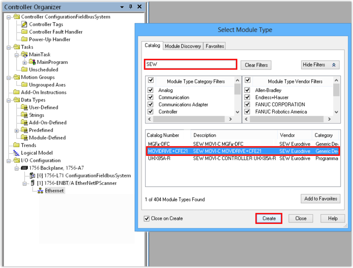
- Add the MOVIDRIVE® technology application inverter from the hardware catalog to the network.
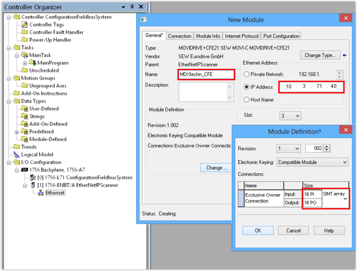
- Enter the IP address of the application inverter. The PLC will address the device using this IP address.
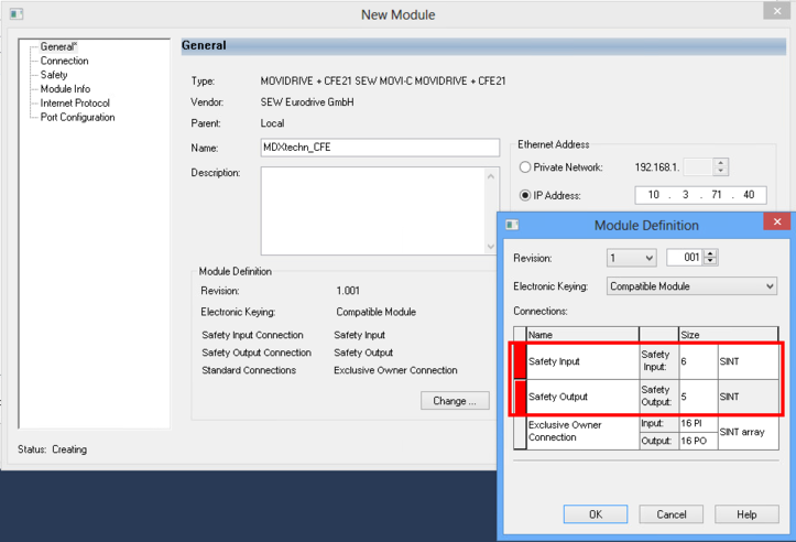
- 2 safety slots are created as standard. If you do not use the safety slots, they must be deleted. To do so, right-click the red bar and select Delete from the context menu.
- Select the number of process data words that you wish to use for communicating with the subordinated slaves. Set the data format for the process data words.
- Up to 16 process data words can be created. If you use a MOVIKIT® software module, SEW‑EURODRIVE recommends that you set the following matching number of process data words:
Software module | Number of process data words (PD) |
|---|---|
MOVIKIT® Velocity Drive | 5 PD |
MOVIKIT® Positioning Drive | 9 PD |
- Establish a communication path between engineering PC and EtherNet/IP™ scanner (PLC) and load the project into the PLC.
