Integrating the inverter into an EtherNet/IP™ network
The following device topology is used in the example:
- Higher-level Allen-Bradley controller ControlLogix® 1756-L71
- MOVIDRIVE® technology MDX9.. application inverter
- USM21A interface adapter
The following figure is a schematic representation of the device topology:
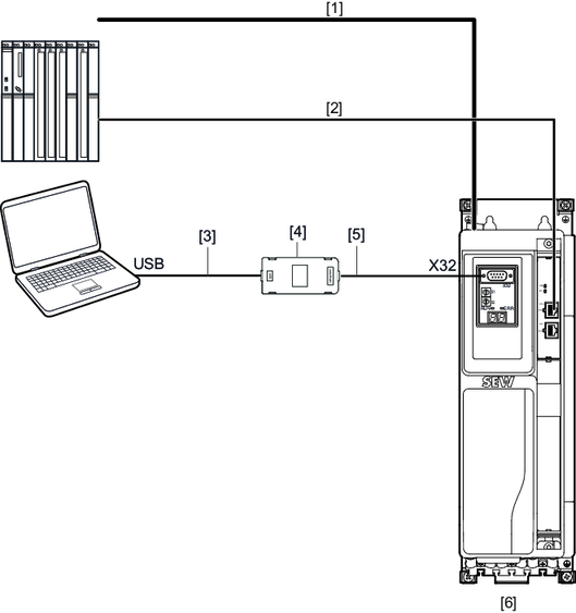
[1] | DC 24 V supply voltage |
[2] | Fieldbus connection |
[3] | USB connection cable, type USB A‑B |
[4] | USM21A interface adapter |
[5] | Serial interface cable with RJ10 connector and 9‑pin D‑sub connector |
[6] | MOVIDRIVE® technology |
For configuration and startup of the devices, the following tools are used:
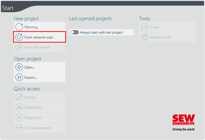
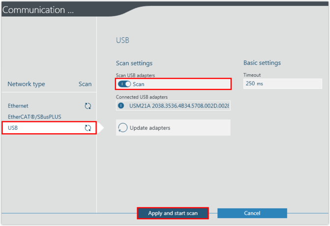
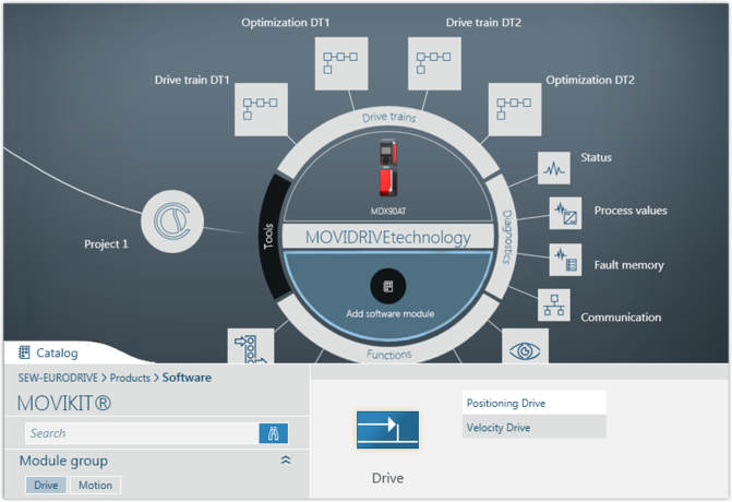
- MOVISUITE® for inverters from SEW‑EURODRIVE
- Studio 5000 Logix Designer from Rockwell Automation for the PLC
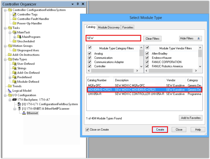
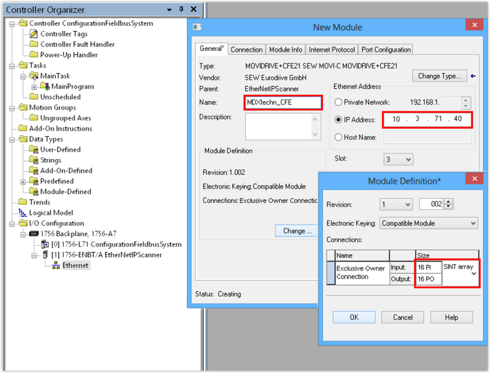
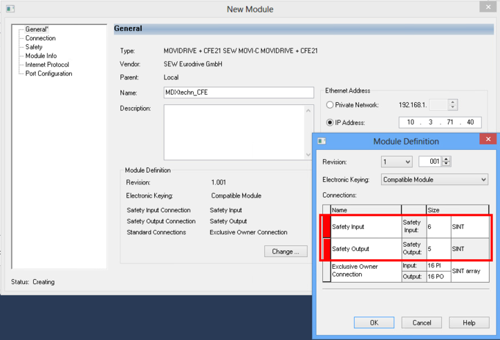
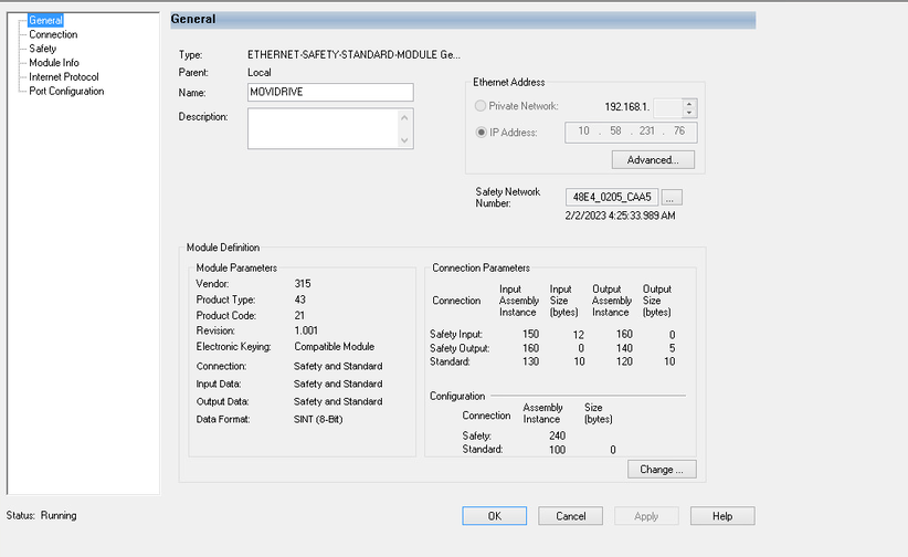
The application inverter is integrated into the EtherNet/IP™ network in several process steps:
Additional information