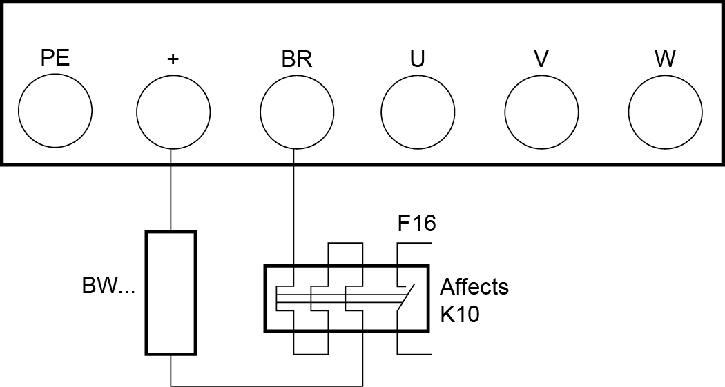
Braking resistor connection

WARNING

Danger of electric shock. The supply cables to the braking resistors carry a high DC voltage (approx. DC 900 V) during nominal operation.
Severe or fatal injuries.
- Before removing the supply cable, disconnect the inverter from the power supply and wait at least 10 minutes.

CAUTION

Risk of burns. The surfaces of the braking resistors reach high temperatures when a load of PN is applied.
Minor injuries.
- Choose a suitable installation location.
- Do not touch the braking resistors.
- Install a suitable touch guard.
The braking resistor is connected between the inverter terminals "BR" and "+". In the case of a new device, these terminals have covers installed that can be broken out. Break out the covers prior to first use.
- Shorten the cables to the required length.
- Use 2 tightly twisted cables or a 2-core shielded power cable. Dimension the cable cross section according to the tripping current IF of F16 and the nominal voltage in accordance with DIN VDE 0298.
- Protect the braking resistor with a bimetallic relay and set the tripping current IF of the respective braking resistor.
- The flatpack resistors have internal thermal overload protection (fuse cannot be replaced). Install the flatpack resistors using appropriate touch guards.
- For braking resistors of the BW...-...-T series, you can connect the integrated temperature sensor using a 2-core, shielded cable as an alternative to a bimetallic relay.
