Wiring diagram

WARNING

Danger of electric shock. Incorrect wiring can lead to dangerously high voltages.
Severe or fatal injuries.
- Adhere to the following points.
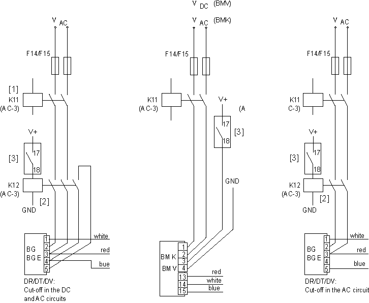
In the following applications, always deactivate the brake on the AC- and DC-side:
- All lifting applications.
- Applications that require a quick brake reaction time.
Observe the following information:
- The following inverters with degree of protection IP66/NEMA 4X already have openings for supply system, motor and control cables.
- 200 – 240 V: 0.75 – 11 kW
- 380 – 480 V: 0.75 – 22 kW
- 500 – 600 V: 0.75 – 30 kW
- The following inverters with degree of protection IP55/NEMA 12K are equipped with a metal entry plate. The user can drill the cable entries according to requirements.
- 200 – 240 V: 5.5 – 75 kW
- 380 – 480 V: 11 – 160 kW
- 500 – 600 V: 15 – 110 kW
- 480 – 525 V: 132 – 200 kW
- The following inverters with degree of protection IP55/NEMA 12K already have openings for supply system, motor, braking resistor, communication, and control cables.
- 380 – 480 V: 200 – 250 kW
- Connect the brake rectifier via a separate supply system cable.
- Supply via the motor voltage is not permitted!
INFORMATION

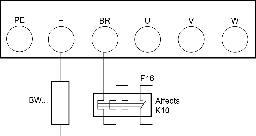
In case of a new device, the terminal locations DC-, + (DC+) and BR are initially provided with break-out covers. These must be broken out if required.

[1] | Line contactor between supply system and inverter |
[2] | Brake |
[3] | Main switch (only for unit design IP66/NEMA 4X housing with switch (MC LTP-B..-40)) |
[4] | Connection of BW../BW..T braking resistor |
[5] | Bimetallic relay for protection of the braking resistor |
[6] | Line choke (optional) |
[7] | Line filter (optional) |
* not with single-phase 230 V
Additional information

