Configuring FSoE slave
The FSoE slave is included in the safety project by an alias device.
In order to establish FSoE communication, the alias device must be linked to the FSoE slots in the FSoE master, the safety parameters of the FSoE slave must be set and the safety functions must be assigned.
Proceed as follows:
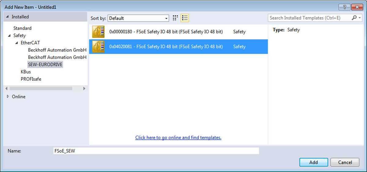
- In the project management, right-click to open the shortcut menu of the "Alias Device" entry in the [SAFETY] > [TwinSafeGroup] area, and select the [Add New Item] menu command.
- Assign a name and click the [Add] button.
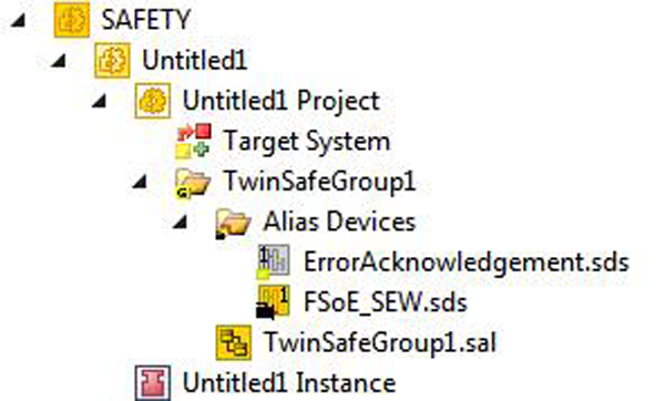
- The alias device is created.
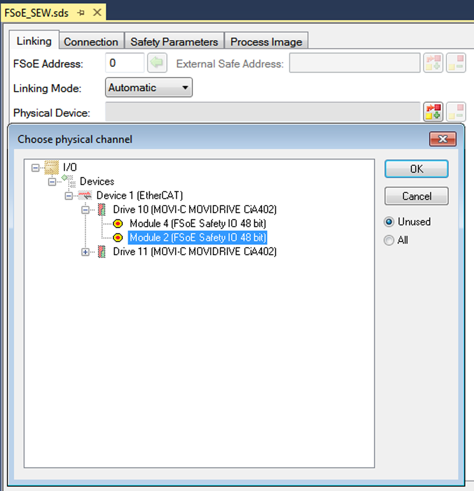
- Double-click the alias device and select the "Linking" tab. Under Physical Devices, select the appropriate entry from the list of all configured FSoE slots.
- Click the [OK] button.
- The alias device is linked to the FSoE slave.
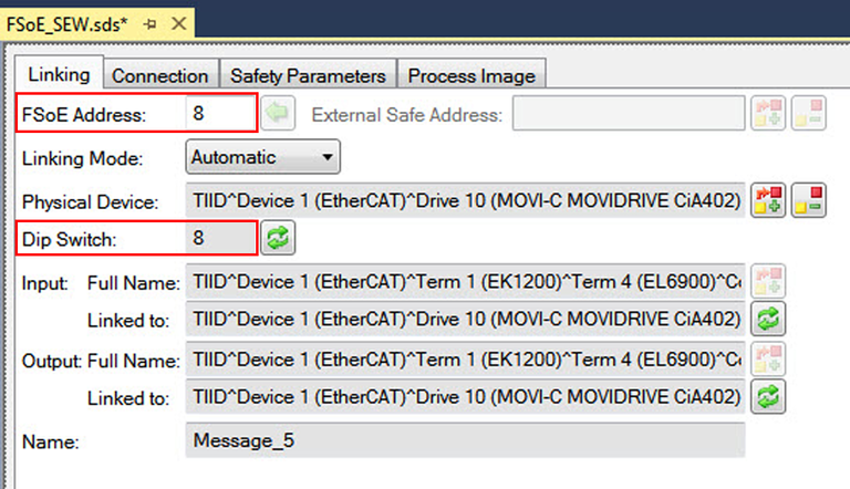
- Enter the FSoE address. The address must match the value in the Dip Switch entry.
- Make sure that the F-address of the FSoE slave is identical to the F-address of the inverter in the MOVISUITE® project. If the TWINCAT program is in the "RUN" operating mode, you can read out the F-address of the inverter.
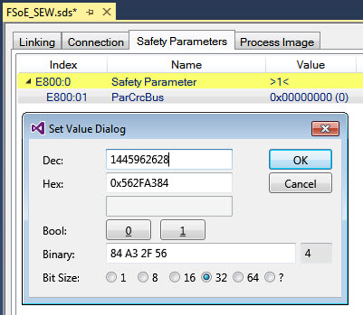
- Switch to the "Safety Parameters" tab. Enter the iPAR_CRC checksum.
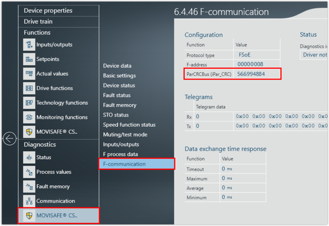
- The value of the checksum must match the accepted checksum ParCRCBus (iPar_CRC) of the MOVISAFE® CS..A safety card. The values for the accepted checksum ParCRCBus (iPar_CRC) can be found in MOVISUITE® under [Diagnostics] > [MOVISAFE® CS..] > [F-communication].
- Link the desired safety functions in the safety program. You can read the assignment of the FSoE process data words and the bitwise assignment of the safety functions from the MOVISUITE® project. Note that the safety functions are always 0-active. A 0-active function is considered to be fulfilled if the linked digital signal has the logical value 0.