Integrating and configuring an inverter into or in the PROFINET network
The inverter must be added to the TIA Portal project, connected with the PLC, and configured.
During configuration, the inverter is assigned a logical name, an IP address, and process data with addresses.
Proceed as follows:
- You have already downloaded the device description file () of the inverter from the SEW‑EURODRIVE website (http://go.sew/os/dud) and saved it locally on the engineering PC.
- Start the TIA Portal and create a new TIA Portal project.
- Install the device description file in the TIA Portal.
- Add the PLC to the project. Assign a PROFINET device name and enter the IP address parameters of the PLC.
- Insert the IO system at the PROFINET interface of the PLC.
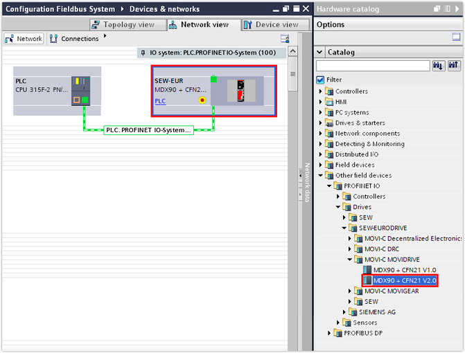
- Open the hardware catalog. Under [Other field devices] > [PROFINET IO] > [Drives] > [SEW-EURODRIVE] > [MOVI-C MOVIDRIVE], select the entry for the MOVIDRIVE® technology application inverter and assign this entry in the network view of the PLC.
- In the inspector window (lower editor section), enter the IP address parameters of the inverter in the "Ethernet addresses" section.
- Assign a PROFINET device name to the inverter. Make sure that the PROFINET device name is identical to the PROFINET device name in the MOVISUITE® project.
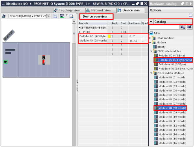
- Add the required number of process data words from the hardware catalog using drag and drop. Alternatively, you can add the process data words by double-clicking the module in the device overview. They will be inserted at the proper slot automatically.
- In this example, the process data words of the MOVIDRIVE® technology application inverter with integrated MOVISAFE® CSS21A safety option (4/3 bytes, V2.6) are made available on the first slot for safe communication. For the assignment of the matching PROFIsafe module to the respective safety option, refer to chapter Device description file of MOVISAFE® CS..A safety options.
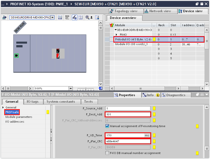
- In the inspector window (lower editor section), enter the safety parameters determined from the acceptance report into the "PROFIsafe" group (see F_iPar_CRC):
- The value of the safety parameter F-address under F_Dest_Add
- The value of the ParCRCBus safety parameter under F_iPar_CRC
- Set the watchdog time (F_WD_Time) to at least 3 or 4 times the cycle time of the safety program.
INFORMATION

Slot 1 is reserved for PROFIsafe. Only 1 PROFIsafe module can be plugged per basic device.
You can add standard process data words to the device overview from slot 2.
For the amount of process data words currently parameterized in the inverter, refer to the MOVISUITE® engineering software. For further information about the assignment of process data words, refer to chapter Process data configuration.