Startup with options MBG11A or MLG..A

WARNING

Electric shock from capacitors that have not been fully discharged.
Severe or fatal injuries.
- Disconnect the inverter from the power. Observe the minimum switch-off time after disconnection from the supply system:
- 1 minute
- Remove the MOVIMOT® inverter from the connection box.
- Check whether the MOVIMOT® drive is installed correctly both mechanically and electrically.
- Refer to chapters "Mechanical Installation" and "Electrical Installation".
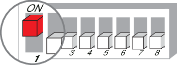
- Set the MOVIMOT® DIP switch S1/1 to "ON" (= address 1).
- Set the minimum frequency fmin using the switch f2.

f2 switch: | |||||||||||
|---|---|---|---|---|---|---|---|---|---|---|---|
Detent position | 0 | 1 | 2 | 3 | 4 | 5 | 6 | 7 | 8 | 9 | 10 |
Minimum frequency fmin [Hz] | 2 | 5 | 7 | 10 | 12 | 15 | 20 | 25 | 30 | 35 | 40 |
- Set the ramp time using switch t1.
- The ramp time is based on a setpoint step change of 1500 min-1 (50 Hz).

t1 switch | |||||||||||
|---|---|---|---|---|---|---|---|---|---|---|---|
Detent position | 0 | 1 | 2 | 3 | 4 | 5 | 6 | 7 | 8 | 9 | 10 |
Setpoint f2 [Hz] | 0.1 | 0.2 | 0.3 | 0.5 | 0.7 | 1 | 2 | 3 | 5 | 7 | 10 |
- Check to see if the required direction of rotation has been enabled.
Clockwise/stop | Counterclockwise/stop | Meaning |
|---|---|---|
Activated | Activated |
|
| ||
Activated | Not activated |
|
| ||
Not activated | Activated |
|
| ||
Not activated | Not activated |
|
| ||


- Place the MOVIMOT® inverter onto the connection box and screw it in place.
- Set the maximum speed required using setpoint potentiometer f1.
- Make sure the screw plug of the setpoint potentiometer has a seal and screw it in.
- Switch on the DC 24 V control voltage and the line voltage.
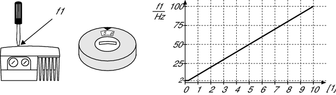
| [1] | Potentiometer setting |
INFORMATION