Connection diagram MOVIMOT® flexible DBC
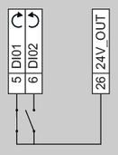
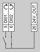
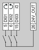
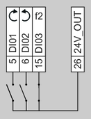
The following figure shows the connections of the device:

[1] | Connection unit option, see chapter Type designation of MOVIMOT® flexible DBC |
[2] | Optional connection for series connection of motor temperature sensors when a maximum of 3 motors are connected. For further connection diagrams, refer to chapter Connection diagrams for MMF32 group drive in the product manual |
[3] | Jumpers installed at the factory for designs without connectors with STO function. For further information, refer to chapter Connection variants of the STO safety subfunction in the product manual. |
For the terminal assignment, refer to chapter Terminal assignment of MOVIMOT® flexible DBC.
For the positions of the connectors, refer to chapter "Connectors" > MMF1 design, MMF31 design, MMF32 design, DBC electronics cover.
For further information regarding the brake control, refer to the product manual > chapter "Technical data" > Brake control.