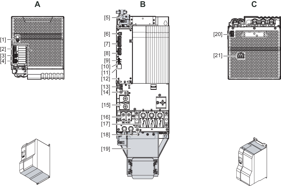
MDR9.B.. supply and regenerative modules
A | View from top |
[1] | EMC: Terminal screw for TN/TT systems |
[2] | X7: Braking resistor temperature monitoring |
[3] | X30 OUT: System bus |
[4] | X30 IN: System bus |
|
|
B | View from front |
[5] | Signal and control cable shield plate |
[6] | X31: SEW‑EURODRIVE Service interface |
[7] | X20: Digital inputs |
[8] | X21: Digital outputs |
[9] | EtherCAT® ID switch |
[10] | Status LEDs EtherCAT® "RUN", "ERR" |
[11] | 7-segment display |
[12] | S3: Switch for module bus operating mode |
[13] | X5: 24 V supply voltage connection |
[14] | PE busbar connection |
[15] | X4: DC link busbar |
[16] | X3: Braking resistor connection |
[17] | X1: Supply system connection |
[18] | 3 × housing PE connection |
[19] | Signal and power cable shield plate |
|
|
C | View from below |
[20] | X13: Line contactor control, precharge inhibit |
[21] | X12: MDR90B: Line voltage tapping from filter module MDR91B: no function |
