Connecting a safe brake module to the DC link

DANGER
Dangerous voltages of up to DC 970 V can occur.
Death or severe injuries due to electric shock.
To prevent electric shocks:
- After disconnection from the power supply, wait at least 10 minutes and ensure that there is no voltage present before you start working on the power connections.
- After maintenance work, do not operate the axis system unless you have replaced the safety covers because the unit only has degree of protection IP00 without the cover.
The SBM safe brake module is directly supplied from the DC link. For connecting a safe brake module to the DC link, a set of angled bars is available in 2 sizes.
The angled bars are screwed to the DC link busbars in the last axis module on the right side or in the power supply module on the left side. Use a M4 screw to fasten a ring cable lug. Use suitable cable lugs for M4 screws.
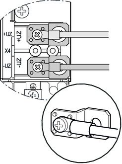
In case of a two-row design with MDC90A-0001-.. or MDC90A-0002-.. capacitor module, the safe brake modules can be connected directly to the capacitor module at terminal X4. In this case, no angled bars are required.
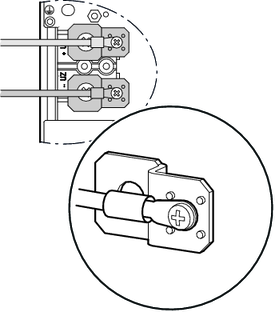
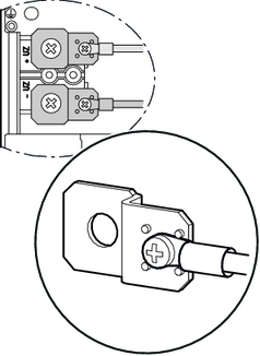
| Cable design to the left | Cable design to the right |
|---|---|---|
Wide bars (20 mm) Large right-angle bar set 28249682 |
|
|
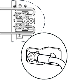
Narrow bar (14 mm) Small right-angle bar set 28249674 |
|
|
Only the SBM safe brake module may be connected to the angled bars.
For more information on the electrical installation of the SBM safe brake module, refer to the associated operating instructions.
