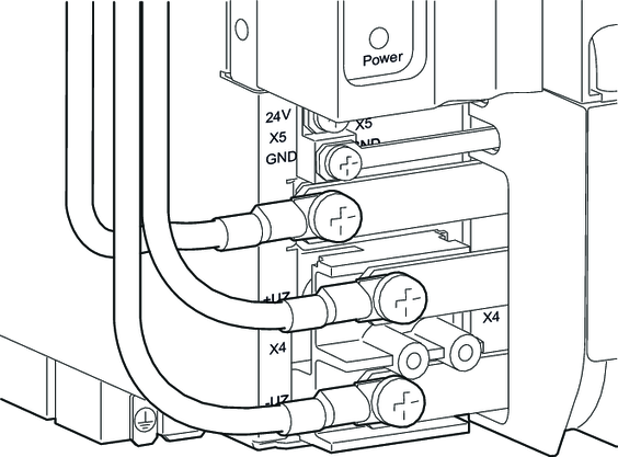
2-row setup of the axis system
If the width of the axis system is wider than the available control cabinet width, it is possible to install some of the modules in a second row (auxiliary row). Observe the following project planning criteria for the 2-row setup of an axis system.
Observe the following information:
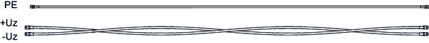
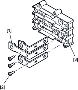
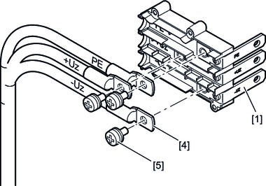
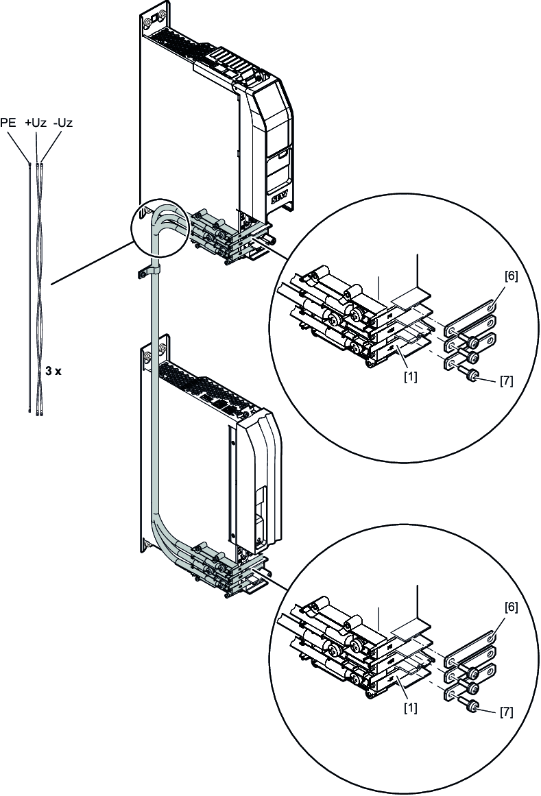
- Use the cable sets from SEW-EURODRIVE for the DC link connection for a 2-row setup, see chapter Wiring harnesses and accessories for 2-row setup.
- Route the signal cables separately from the power cables.
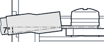
- Route the motor cables on the left side of the axis blocks. To avoid mechanical vibration, fix the DC link connection with suitable means, e.g. with a clamp [7]. Consider any oscillations and vibrations, especially in mobile control cabinets.
- Route the DC link connection on the left side of the axis blocks. To avoid mechanical vibration, fix the DC link connection with suitable means, e.g. with a clamp. Consider any oscillations and vibrations, especially in mobile control cabinets.
Two-row setup
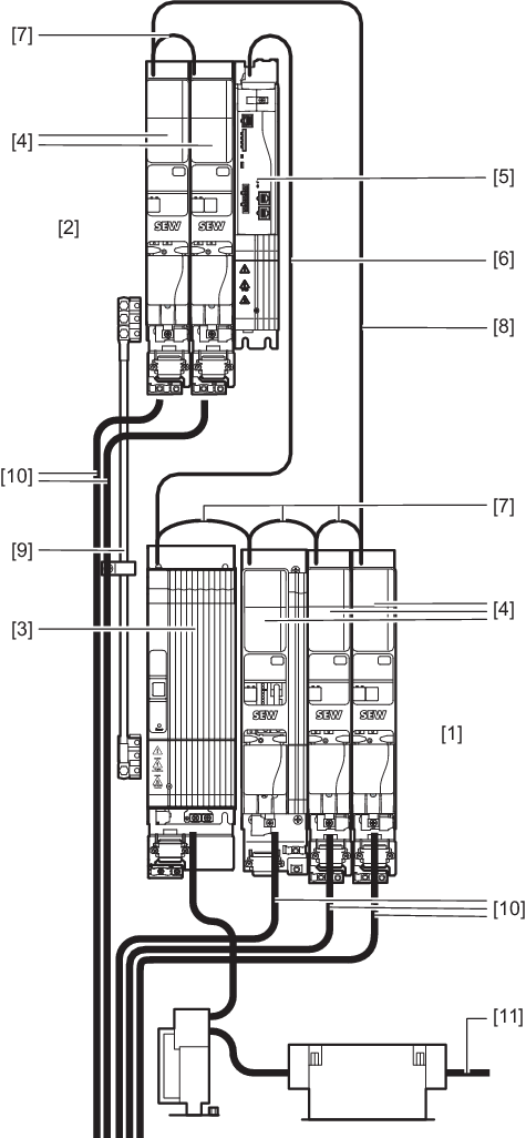
[1] | Main row |
[2] | Auxiliary row |
[3] | Power supply module |
[4] | Axis module |
[5] | Master module |
[6] | System bus cable between master module and power supply module |
[7] | Module bus cable for module wiring in one row |
[8] | Module bus connection cable between main row and auxiliary row |
[9] | Cables for DC link connection |
[10] | Motor lead |
[11] | Supply system cable |
For more information on the cables, refer to the Product manual > chapter Prefabricated cables.