Project planning example
The following project planning example shows the project planning of the 24 V voltage supply for an axis system.
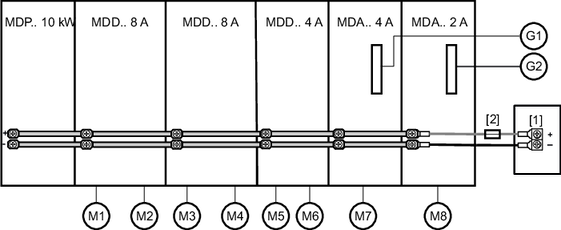
[1] | 24-V voltage supply | G | Encoder |
[2] | DC 24 V fuse | M | Motor |
Modules and devices used in the axis system:
- 8 brakemotors – 4 × CMP63S with BK03, 4 × CMP50M with BK02
- 8 motor encoders in the basic device
- 2 external encoders with CES11A option
- 8 × 4 digital outputs in the axis modules
- 1 MDP.. power supply module 10 kW
- 2 MDD.. double-axis modules 8 A
- 1 MDD.. double-axis module 4 A
- 1 MDA.. single-axis module 4 A
- 1 MDA.. single-axis module 2 A
The total power consumption is calculated from the total power consumption of all used modules, cards, and externally connected devices.
- 4 × brake BK03: 4 × 14 W = 56 W
- 4 × brake BK02: 4 × 7 W = 28 W
- 8 × motor encoder: 8 × 5 W = 40 W
- 2 × external encoder: 2 × 12 W = 24 W
- 2 × CES11A card: 2 × 0.8 W = 1.6 W
- 8 × 4 digital outputs in the axis modules 8 × 4 × 1.2 W = 38.4 W
- 1 MDP.. power supply module 10 kW: 15 W
- 2 MDD.. double-axis modules 8 A: 2 × 22 W = 44 W
- 1 MDD.. double-axis module 4 A: 20 W
- 1 MDA.. single-axis module 4 A: 20 W
- 1 MDA.. single-axis module 2 A: 20 W
Select the external 24 V supply to ensure that the sum of the individual power levels is 307 W, and the resulting current is 12.8 A.
Check whether one-sided or two-sided supply: 12.8 A < 40 A → one-sided supply
