Assigning the EtherCAT/SBusPLUS address
To set the EtherCAT®/SBusPLUS address, two hexadecimal address switches S1 and S2 are installed on the power supply module and the DC/DC converter module. For information on the installation position of the switches, refer to chapter Device structure. A hexadecimal address between 1 and FF is set here. This address can be converted into a decimal address using the table below.
The following table lists example settings for the address switches:
Required address, decimal | Address, hexadecimal | Setting S1 (× 16) | Setting S2 (× 1) |
|---|---|---|---|
3 | 03 | 0 | 3 |
18 | 12 | 1 | 2 |
25 | 19 | 1 | 9 |
100 | 64 | 6 | 4 |
110 | 6E | 6 | E |
255 | FF | F | F |
S1 address switch |
| 6 |
S2 address switch |
| E |
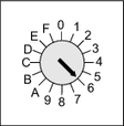
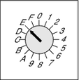
The EtherCAT®/SBusPLUS address "110" is set as an example in the illustration above.
