Requirements when combining the modules in a network
In this chapter, you can find conditions for the use of the switched-mode power supply modules and sample combinations. The examples show how the individual devices are arranged in the network. The structure of a network of devices consisting of power supply module and axis modules is described in the documentation "MOVIDRIVE® modular application inverter".
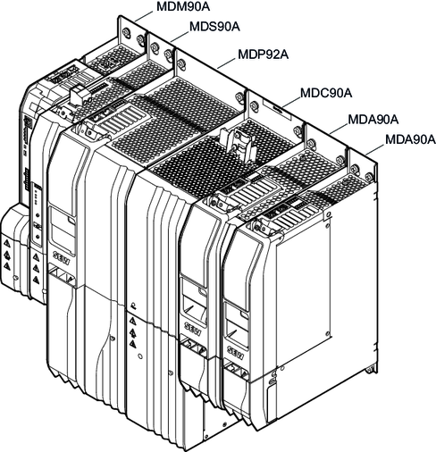
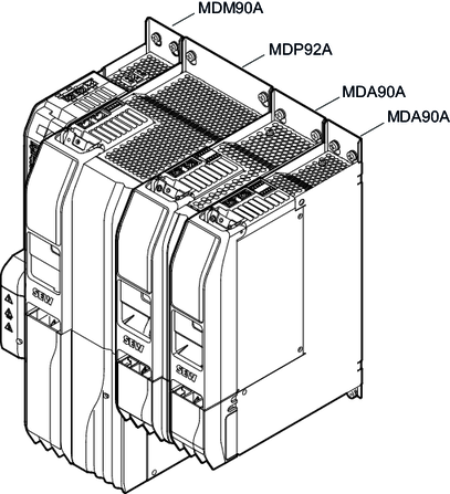
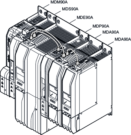
Structure of a device network:
- A maximum of 16 devices with a module bus connection can be combined in a network. Devices with a module bus connection are power supply modules and axis modules.
- Axis modules MDA90A/MDD9.A must be installed to the right of the MDP92A power supply module, the DC/DC capacitor module or the MDC90A-0120-.. capacitor module.
- Switched-mode power supply modules with AC and DC supply MDS90A must be attached to the left of the MDP92A/MDP90A power supply module or the MDE90A DC/DC converter module. A maximum of 6 switched-mode power supply modules can be combined in a network.
- MDC90A-0120-.. capacitor modules must be installed to the right of the MDP92A power supply module or the MDE90A DC/DC converter module. An MDC90A-0120-.. capacitor module can only be used in combination with an MDP92A power supply module or an MDE90A DC/DC converter module. A maximum of 4 capacitor modules can be combined in a network.
- If an MDE90A DC/DC converter module is used in combination with an MDP92A/MDP90A power supply module, the MDE90A must be mounted to the left of the power supply module.
Additional information