Horizontal installation
The following figure shows the minimum clearances of the device:
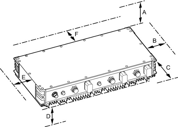
The following table shows the size of the minimum clearances:
Clearance | Function | Size |
|---|---|---|
A: Device cover | Space for display, diagnostics and operating elements, e.g. service unit | ≥ 260 mm |
B: To the side, right | Space for connection cables, plug connectors, mounting elements and operating elements, e.g. maintenance switch | See dimension drawings in the product manual > chapter Technical data
|
C: Front | Space for connection cables and plug connectors | See dimension drawings in the product manual > chapter Technical data |
D: Below the cooling fins | Space for optimum heat convection The cooling fins must not be located in a closed hollow space. | ≥ 15 mm |
E: To the side, left | Space for optimum heat convection | ≥ 30 mm |
F: Rear | Space for optimum heat convection | ≥ 30 mm |
