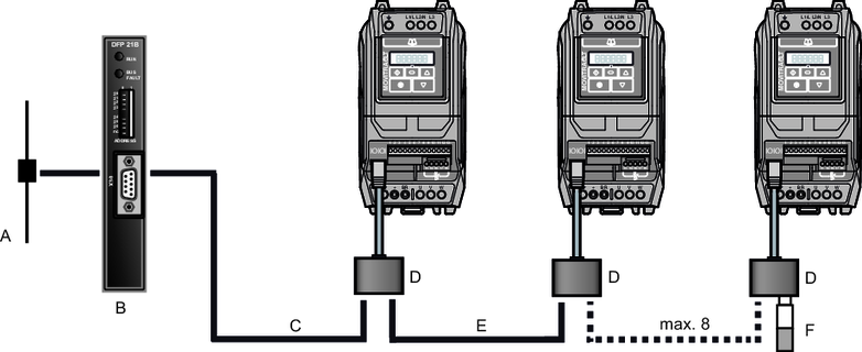
Connecting a gateway or controller (SBus MOVILINK®)
Connection from gateway and MOVI-PLC®.

[A] | Bus connection | [D] | Splitter |
[B] | Gateway, e.g. DFx/UOH | [E] | Connection cable |
[C] | Connection cable | [F] | Y connector with terminating resistor |
INFORMATION

As of firmware version 1.20, a backup mode for maintaining communication in the event of a power failure is possible; this is not possible with older versions. Also observe chapter 24 V backup voltage connection for this.
The terminating connector [F] is equipped with 2 terminating resistors and therefore establishes the terminating connection to CAN/SBus and Modbus RTU.
Instead of a terminating connector from cable set A, you can use the Y adapter from engineering cable set C. This set also includes a terminating resistor. For detailed information on the cable sets, refer to the catalog "MOVITRAC® LTP‑B".
Only use shielded cables for the communication connections and also apply the shielding at the gateway over a large surface area.
Wiring from the controller to the RJ45 communication socket of the inverter:
Side view | Designation | Terminal at CCU/PLC | Signal | RJ45 socket contactObserve the following: The terminal assignment for the socket of the inverter, not for the connector, is specified above. | Signal |
|---|---|---|---|---|---|
MOVI-PLC® or gateway (DFX/UOH) | X26:1 | CAN 1H | 2 | SBus/CAN bus h | |
X26:2 | CAN 1L | 1 | SBus/CAN bus l | ||
X26:3 | DGND | 3 | GND | ||
X26:4 | Reserved |
|
| ||
X26:5 | Reserved |
|
| ||
X26:6 | DGND |
|
| ||
X26:7 | DC 24 V |
|
| ||
Third-party controller | X:?Assignment depends on the third-party controller | Modbus RTU+ | 8 | RS485+ (Modbus RTU) | |
X:?2) | Modbus RTU- | 7 | RS485- (Modbus RTU) | ||
X:?2) | DGND | 3 | GND |

