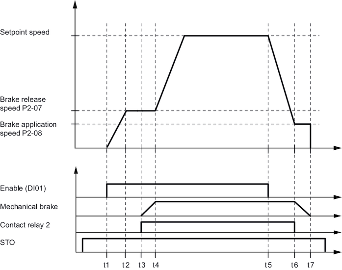
Cycle diagram for lifting operation
The following diagram shows hoisting mode.

t1 | Inverter enable |
t1 - t2 | The motor runs up to brake release speed |
t2 | Brake release speed is reached. |
t2 - t3 | Torque threshold P4-15 verified. The inverter indicates a fault if the torque threshold exceeds the timeout set in P4-16. |
t3 | Relay opens. |
t3 - t4 | Brake opens within brake release time P4-13. |
t4 | Brake is released. The drive runs up to the setpoint speed. |
t4 - t5 | Normal operation |
t5 | Inverter lock |
t5 - t6 | Drive slows down to brake application speed |
t6 | Relay closes. |
t6 - t7 | Brake applied within brake application time P4-14. |
t7 | Brake is closed and drive stopped. |
