Collegamento dell'encoder
NOTA

È possibile utilizzare anche encoder con output single-ended. Per fare ciò, collegare i cavi dell'encoder a +A, +B e +Z. I collegamenti -A, -B e -Z restano liberi.
Tramite gli ingressi encoder è possibile collegare un encoder. Accertarsi che il valore encoder determinato non venga valutato ulteriormente nel modulo. È possibile leggere il valore encoder ed elaborarlo adeguatamente nel proprio programma applicativo.
Encoder:
- 5 V, segnale TTL
- fase A, B e Z
- massimo 1 MHz
- valutazione quadrupla
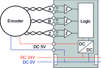
Schema di collegamento |
|---|
|

N. | Nome | I/O | Funzione |
|---|---|---|---|
4 | ENC5V | output | alimentazione di tensione encoder 5 V |
5 | ENC+A | input | input encoder +A (5V/TTL) |
6 | ENC+B | input | input encoder +B (5V/TTL) |
7 | ENC+Z | input | input encoder +Z (5V/TTL) |
13 | ENCoV | output | alimentazione di tensione encoder GND |
14 | ENC-A | input | input encoder -A (5V/TTL) |
15 | ENC-B | input | input encoder -B (5V/TTL) |
16 | ENC-Z | input | input encoder -Z (5V/TTL) |
