Encoder connection
INFORMATION

Encoders with single-ended outputs can also be used. To do this, the wires of the encoder must be connected to +A, +B and +Z. The -A, -B and -Z connections remain open.
You have the option of connecting an encoder via the encoder inputs. Please note that the measured encoder value is not evaluated in the module. You can read out the encoder value and process it accordingly in your user program.
Encoder:
- 5 V, TTL signal
- Phase A, B and Z
- Maximum 1 MHz
- 4-factor evaluation
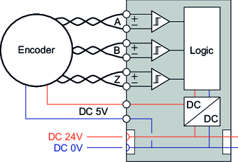
Wiring diagram |
|---|
|

No. | Name | Input/output | Function |
|---|---|---|---|
4 | ENC5V | Output | Encoder voltage supply 5 V |
5 | ENC+A | Input | Encoder input +A (5 V/TTL) |
6 | ENC+B | Input | Encoder input +B (5 V/TTL) |
7 | ENC+Z | Input | Encoder input +Z (5 V/TTL) |
13 | ENCoV | Output | Encoder voltage supply GND |
14 | ENC-A | Input | Encoder input -A (5 V/TTL) |
15 | ENC-B | Input | Encoder input -B (5 V/TTL) |
16 | ENC-Z | Input | Encoder input -Z (5 V/TTL) |
