Block diagram of function module OSS21C
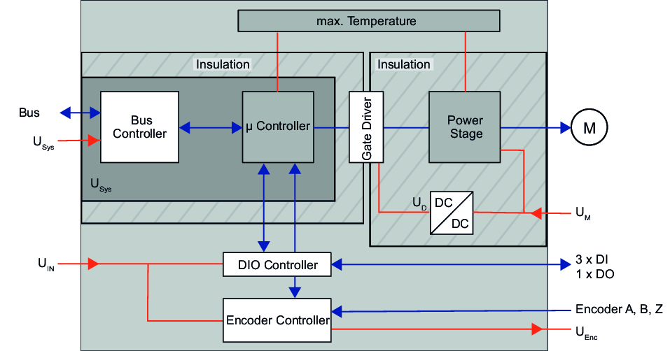
Voltages
|
Vsys |
DC 5 V electronics supply Voltage supply for electronics and backplane bus communication |
|
VIN |
DC 24 V power supply Voltage supply for the I/O level Range: DC 20.4 – 28.8 V |
|
VD |
DC 10 V driver supply The voltage supply consists of M via a DC-DC converter |
|
VM |
Motor voltage supply Range: DC 20.4 – 57.6 V |
|
VENC |
Encoder voltage supply Voltage: DC 5 V, typically 100 mA (maximum 200 mA) |
Behavior in the event of a DC 24 V power supply failure:
- The 5 V encoder voltage supply ENC 5 V fails.
- The encoder counter value stops due to the loss of signal.
- The digital output DO is deactivated
- Digital inputs DI1 and DI2 deliver a constant "1" signal in the process data.
- Digital input DI3 delivers a constant "0" signal in the process data.
- By evaluating digital input DI3, you can monitor the DC 24 V power supply externally.
Nominal current
|
Full-step operation |
|
|
Microstep mode |
|
|
Wiring of the windings |
|
Temperature monitoring
The function module is equipped with internal temperature monitoring of the μ-controller and the output stage. You can define limit temperatures in the object list. If a limit value is exceeded or not reached, the function module triggers a configurable error response.
INFORMATION

At an ambient temperature of 60 °C and high load on the function module and neighboring modules with high power loss, small areas of the housing can reach temperatures higher than 85 °C. This is compliant with DIN EN 61010-2-201:2019-04.
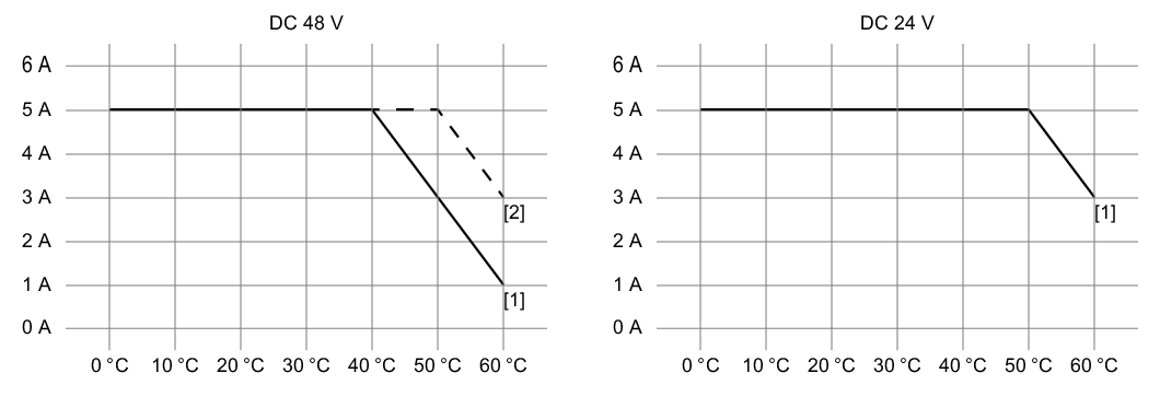
Observe the following derating for the motor current for the corresponding motor supply voltage:
|
[1] |
Vertical installation |
|
[2] |
Horizontal installation |
